De-icing arrangement and method for de-icing a structural element

a structural element and arrangement technology, applied in the direction of rotors, vessel construction, piezoelectric/electrostrictive device details, etc., can solve the problems of ice accretion being a threatening event, serious perturbation of flying conditions, and ice accretion on aircrafts a very complex physical process, so as to improve the de-icing effect of structural elements

Inactive Publication Date: 2015-10-22
SAAB AB
View PDF36 Cites 10 Cited by
  • Summary
  • Abstract
  • Description
  • Claims
  • Application Information

AI Technical Summary

Benefits of technology

[0007]One objective of the present invention is to provide an improved de-icing of a structural element, such as a wing of an aircraft or a blade of a wind power installation.

Problems solved by technology

Aircrafts are continuously exposed to varying climatic conditions and in this regard, ice accretion is a threatening event.
Ice accretion is known to cause serious perturbations to the flying conditions due to ice formations on aerodynamic surfaces of aircraft.
Ice accretion on aircrafts is a very complex physical process.
The selection of an adequate ice rejection technique is thus a difficult task.
One of the issues is the growing need for fuel consumption reductions.
Especially when using electromechanical de-icing systems (EMEDS) also the power output for driving the de-icing system is an issue and it is desirable to minimize the peak power output for the electromechanical de-icing system.

Method used


Image

  • De-icing arrangement and method for de-icing a structural element
  • De-icing arrangement and method for de-icing a structural element
  • De-icing arrangement and method for de-icing a structural element

Examples


Embodiment Construction

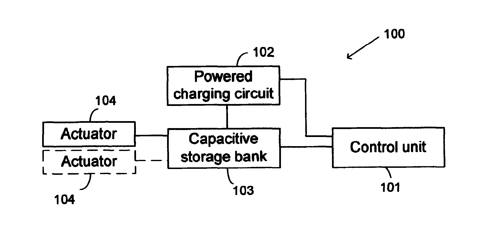
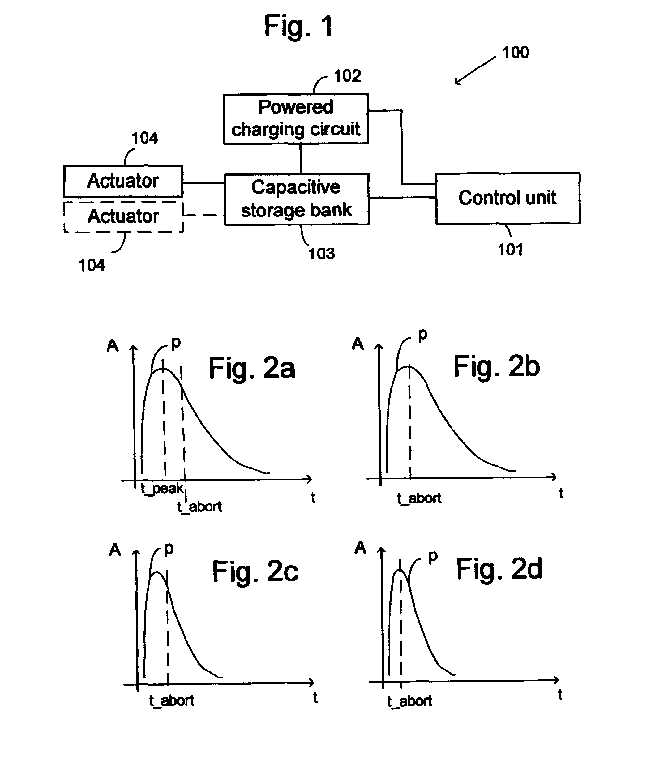
[0038]A de-icing arrangement for de-icing a structural element comprises at least one actuator for removing ice from the structural element, a capacitive storage bank and a control unit arranged to control discharge of the capacitive storage bank to provide an excitation pulse to the at least one electromagnetic actuator so as to force the actuator to apply a mechanical force on the structural element so as to provide a chock in the structural element. This may result in removal of ice from the structural element. The actuator is arranged to expand in at least one direction when fed with the excitation pulse. The actuator is arranged in relation to the structural element so that mechanical force caused by the expansion on the structural element will be applied to the structure element.

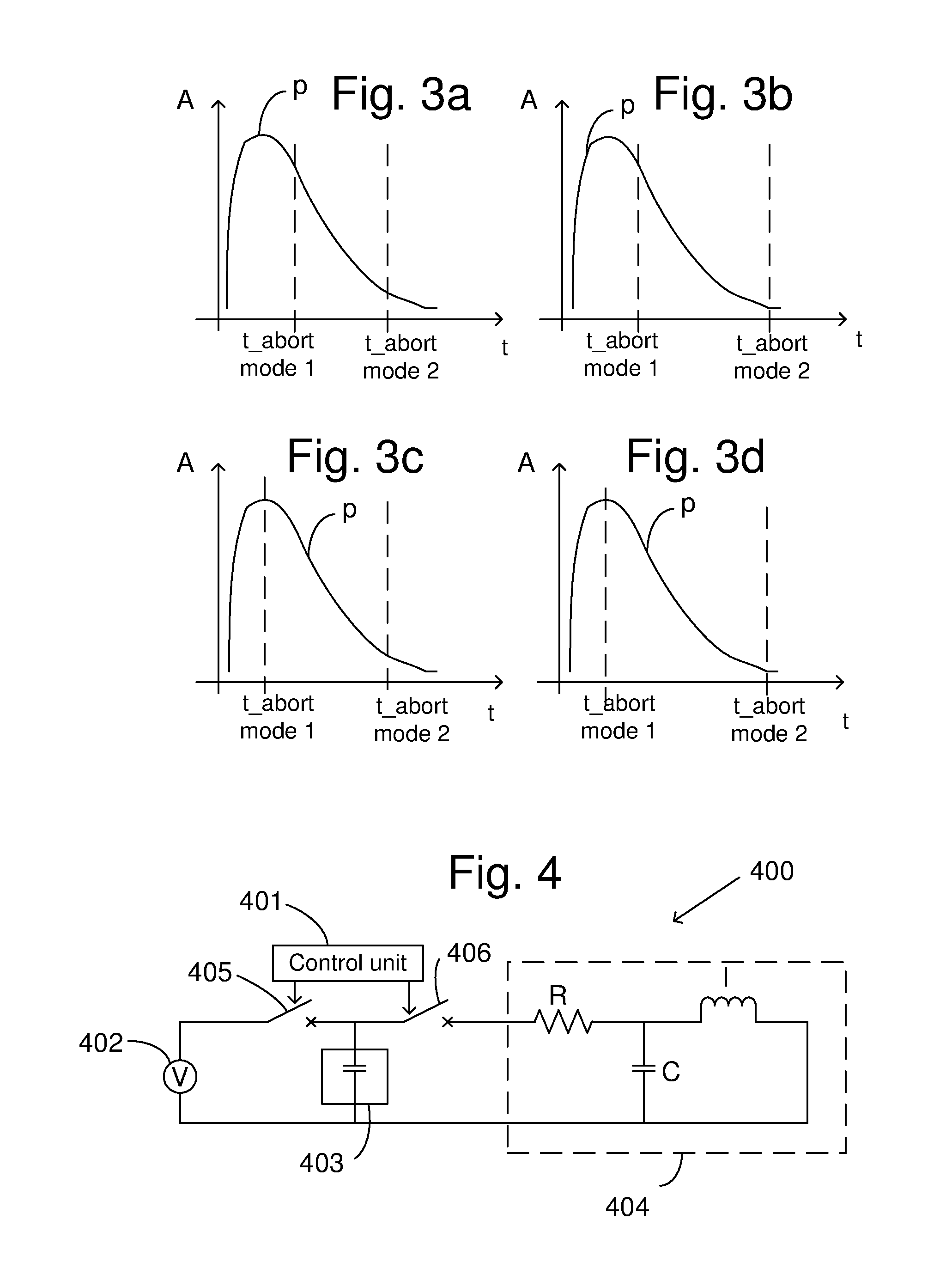
[0039]The control unit is arranged to control cutoff of discharge of the capacitive storage bank and thus controlling abortion of the excitation pulse into the at least one electromagnetic actuator.

[00...


PUM


Abstract

A de-icing arrangement and a method for de-icing a structural element. The de-icing arrangement includes at least one electromagnetic actuator, a capacitive storage bank, a control unit arranged to provide an excitation pulse to the at least one electromagnetic actuator, and a charging circuit arranged to charge the capacitive storage bank. The at least one electromagnetic actuator is arranged to expand in at least one direction when fed with the excitation pulse. The at least one electromagnetic actuator is arranged in relation to the structural element so as to apply a mechanical force caused by the expansion on the structural element. The control unit is arranged to control cutoff of current discharge of the capacitive storage bank into the at least one electromagnetic actuator so as to abort the excitation pulse at a predetermined timing after start of the excitation pulse.

Description

TECHNICAL FIELD[0001]The present invention relates to a de-icing arrangement and method for de-icing a structural element by means of at least one electromagnetic actuator.BACKGROUND ART[0002]Aircrafts are continuously exposed to varying climatic conditions and in this regard, ice accretion is a threatening event. Ice accretion is known to cause serious perturbations to the flying conditions due to ice formations on aerodynamic surfaces of aircraft.[0003]Ice accretion on aircrafts is a very complex physical process. The selection of an adequate ice rejection technique is thus a difficult task. The technique to be selected must be made compatible with a number of constraints comprising material properties, fatigue, dynamic deformation while in flight, repairing and servicing constraints, durability etc, just to name a few.[0004]One of the issues is the growing need for fuel consumption reductions. Especially when using electromechanical de-icing systems (EMEDS) also the power output ...

Claims


Application Information

Patent Timeline
Patent Type & Authority Applications(United States)
IPC IPC(8): H01L41/04F03D11/00
CPCF03D11/0025H01L41/042B64D15/163F03D80/40Y02E10/72H10N30/802
Inventor HADEN, BERTILBACKSTROM, MATS
Owner SAAB AB
Why Eureka
Try Eureka