Self-oscillating resonant power converter

a resonant power converter and self-oscillating technology, applied in the direction of electric variable regulation, process and machine control, instruments, etc., can solve the problems of inability to quickly and accurately control inability to switch, and inability to achieve fast and accurate control of the output voltage of the resonant power converter, etc., to achieve the effect of fast switch turn-on and turn-off times

Active Publication Date: 2015-10-22
DANMARKS TEKNISKE UNIV
View PDF3 Cites 60 Cited by
  • Summary
  • Abstract
  • Description
  • Claims
  • Application Information

AI Technical Summary

Benefits of technology

[0024]In another embodiment, the self-oscillating feedback loop comprises a series resonant circuit coupled in-between the control input of the first semiconductor switch and a fixed electric potential of the converter. The series resonant circuit preferably comprises a cascade of capacitor and an inductor connected between the control input of the semiconductor switch and a negative power supply rail e.g. ground. The series resonant circuit functions to introduce additional uneven frequency components, by attenuating one or more even harmonic frequency components, to a fundamental frequency component of the oscillating voltage waveform at the control input of the switching network, e.g. the gate of the first semiconductor switch. This leads to a trapezoidal waveform shape of the oscillating voltage waveform and results in faster switch turn-on and turn-off times.
[0025]A useful embodiment of the present resonant power converter comprises a DC-DC power converter. The DC-DC power converter is preferably constructed or derived by coupling a rectifier between the output of the resonant network and the inverter or converter output terminal to generate a rectified DC output voltage. The rectifier may comprise one or more diodes to provide passive rectification of the DC output voltage. The rectifier of an alternative embodiment of the resonant power converter comprises a synchronous rectifier which may comprise one or more semiconductor switches. According to one such embodiment the synchronous rectifier comprises: a rectification semiconductor switch configured to rectify an output voltage of the resonant network in accordance with a rectifier control input of the rectification semiconductor switch. A first rectification inductor with a substantially fixed inductance is coupled in-between a fixed or adjustable rectifier bias voltage and the rectifier control input. It is a significant advantage of this embodiment that the fixed or adjustable rectifier bias voltage of the rectifier may be left decoupled or unconnected to the first bias voltage source generating the first adjustable bias voltage for the switching network on the input side of the resonant power converter for the reasons discussed in detail below with reference to FIG. 8 of the appended drawings. The fixed or adjustable rectifier bias voltage may for example be coupled to a fixed DC bias voltage source of the resonance power converter or to the rectified DC output voltage through a resistive or capacitive voltage divider.

Problems solved by technology

Resonant power converters are particularly useful for high switching frequencies such as above 1 MHz where switching losses of standard SMPS topologies (Buck, Boost etc.) tend to be unacceptable for conversion efficiency reasons.
However, fast and accurate control of the output voltage of the resonant power converter remains a challenge.
However, the possible regulation range of adjustable inductances and / or capacitances tend to be very narrow due to physical component limitations and the accuracy may also be limited.
Furthermore, adjustable inductances and / or capacitances are difficult to integrate on semiconductor substrates or on ordinary circuit carriers like printed circuit boards.
Finally, the maximum regulation speed of the inductance or capacitance may be limited due to the reactive nature of the component leading to an undesirable limitation of the speed of the regulation of the converter output voltage.
This is of course particularly undesirable in view of the advantages of moving to higher converter switching frequencies for the reasons discussed above.

Method used


Image

  • Self-oscillating  resonant power converter
  • Self-oscillating  resonant power converter
  • Self-oscillating  resonant power converter

Examples


first embodiment

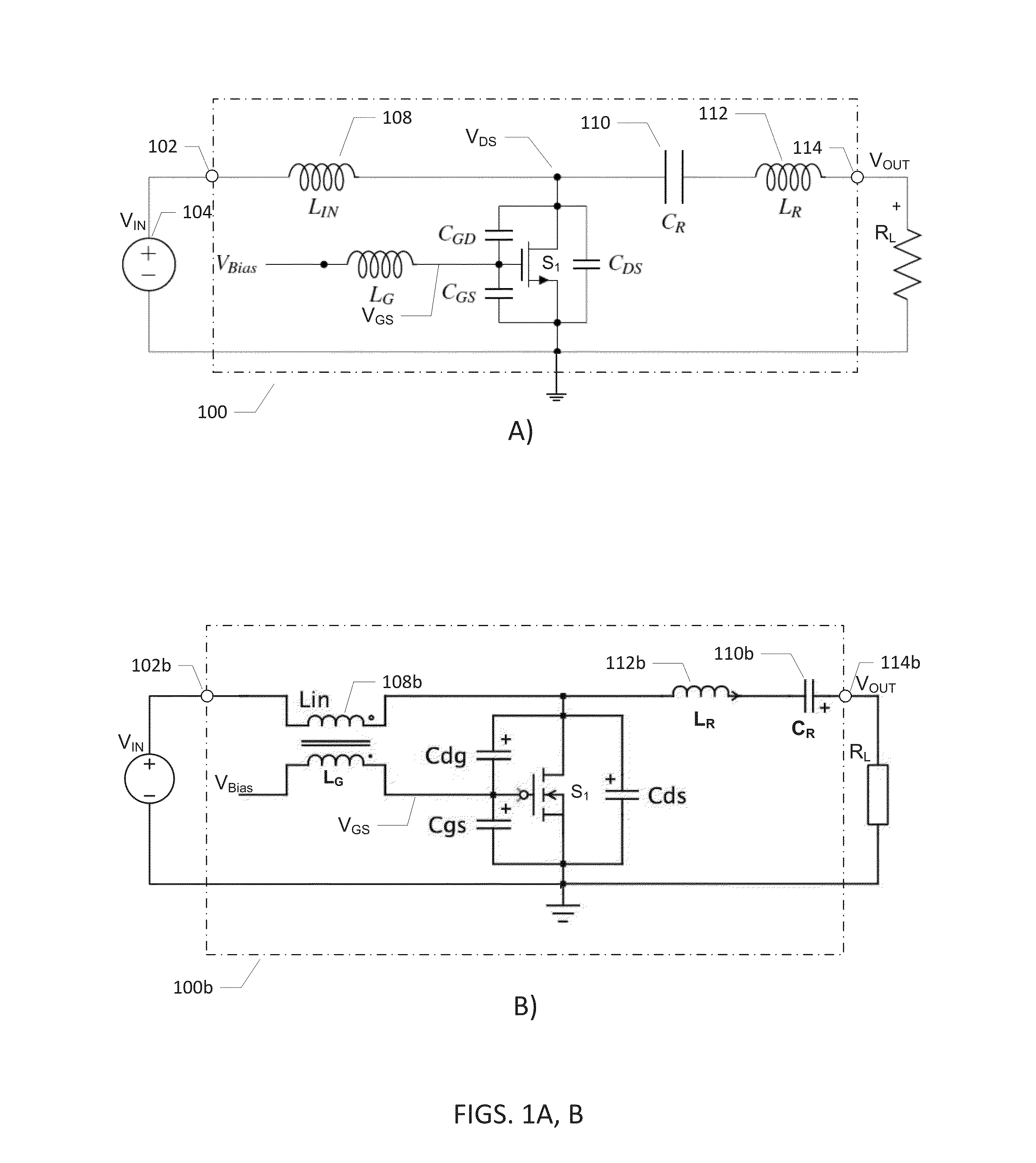
[0044]FIG. 1A) is a simplified electrical circuit diagram of a class E resonant power converter 100 in accordance with the invention. The present class E resonant power converter is particularly well-adapted for operation in the VHF frequency range for example at switching frequencies above 10 MHz or even higher such as between 30 and 300 MHz due to, amongst other factors, low switching losses in connection with the operation of a self-oscillating feedback loop connected around a transistor switch element S1 as explained in further detail below.

[0045]The class E resonant power inverter or converter 100 comprises an input pad or terminal 102 for receipt of a DC input voltage VIN from a DC power supply 104. The DC voltage level may vary considerably according to requirements of any particular conversion application such as lying between 1 V and 500 V for example between 10 V and 230 V. A switching network comprises a single switch transistor S1. The skilled person will understand that...

fourth embodiment

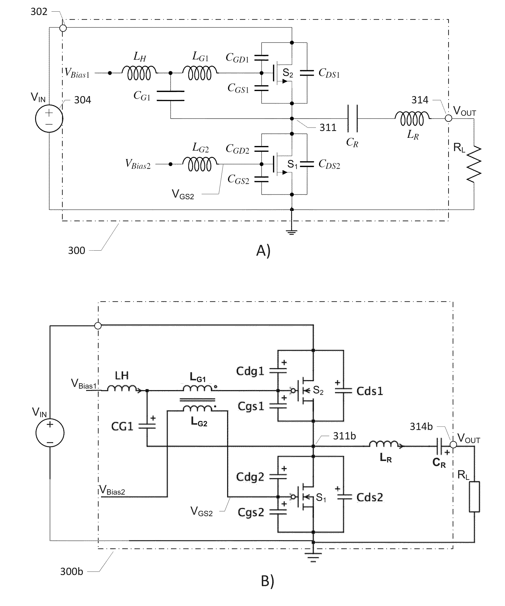
[0073]The DC-DC power converter 800 comprises, in addition to the circuitry of the class E resonant power converter 100, a synchronous rectifier building around transistor switch SR1 and comprising additional passive components LG2 and LOUT. The skilled person will understand that the DC-DC power converter 800 may comprise an output capacitor coupled from VOUT to the negative supply rail (e.g. ground) and a voltage control loop similar to the one discussed above in connection with FIG. 4 in the invention. The voltage control loop being configured to control the output voltage at VOUT of the power converter 800 as defined by a DC or AC reference voltage. The transistor switch element SR1 and inductors LG2 and LOUT provide a synchronous rectifier in the DC-DC power converter 800 and replaces the diode based asynchronous rectifier circuit 413 discussed above. Since the control input, e.g. the gate drive signal, of the switching network of the present class E and DE resonant power conve...


PUM


Abstract

The present invention relates to resonant power converters and inverters comprising a self-oscillating feedback loop coupled from a switch output to a control input of a switching network comprising one or more semiconductor switches (S1, S2). The self-oscillating feedback loop sets a switching frequency of the power converter (100) and comprises a first intrinsic switch capacitance (CGD) coupled between a switch output and a control input of the switching network and a first inductor (LG). The first inductor (LG) is coupled in-between a first bias voltage source and the control input of the switching network and has a substantially fixed inductance. The first bias voltage source is configured to generate an adjustable bias voltage (VBias) applied to the first inductor (LG). The output voltage (V0UT) of the power converter (100) is controlled in a flexible and rapid manner by controlling the adjustable bias voltage (VBias).

Description

[0001]The present invention relates to resonant power converters and inverters comprising a self-oscillating feedback loop coupled from a switch output to a control input of a switching network comprising one or more semiconductor switches. The self-oscillating feedback loop sets a switching frequency of the power converter and comprises a first intrinsic switch capacitance coupled between a switch output and a control input of the switching network and a first inductor. The first inductor is coupled in-between a first bias voltage source and the control input of the switching network and has a substantially fixed inductance. The first bias voltage source is configured to generate an adjustable bias voltage applied to the first inductor. The output voltage of the power converter is controlled in a flexible and rapid manner by controlling the adjustable bias voltage.BACKGROUND OF THE INVENTION[0002]Power density is always a key performance metric of a power supply circuit such as AC-...

Claims


Application Information

Patent Timeline
Patent Type & Authority Applications(United States)
IPC IPC(8): H02M3/158H02M1/00H02M7/5383
CPCH02M3/158H02M3/1588H02M7/5383H02M3/1563Y02B70/10H02M1/0064H02M1/0058H02M1/0006H02M1/08H02M3/3385H02M7/538466
Inventor MADSEN, MICKEY P.PEDERSEN, JEPPE ARNSDORF
Owner DANMARKS TEKNISKE UNIV
Why Eureka
Try Eureka