Linear motor control apparatus and linear motor control system

a control apparatus and linear motor technology, applied in the field of linear motors, can solve the problems of high cost of electric circuits, difficulty in individual control of plurality of trucks on the same conveying path, and difficulty in stopping the truck at a high precision. achieve the effect of high precision

Active Publication Date: 2015-10-22
CANON KK
View PDF8 Cites 49 Cited by
  • Summary
  • Abstract
  • Description
  • Claims
  • Application Information

AI Technical Summary

Benefits of technology

[0011]The invention is made to solve the foregoing problem and it is an aspect of the invention to provide a linear moto

Problems solved by technology

However, it is difficult to individually control the plurality of trucks on the same conveying path.
In this case, since the truck is simultaneously controlled from two motor controllers for respectively controlling the adjacent coil units, it is difficult to stop the truck at a high precision.
On the other hand, in order to allow the truck to obtain a thrust which is equal to that in the case where both of the

Method used


Image

  • Linear motor control apparatus and linear motor control system
  • Linear motor control apparatus and linear motor control system
  • Linear motor control apparatus and linear motor control system

Examples


first embodiment

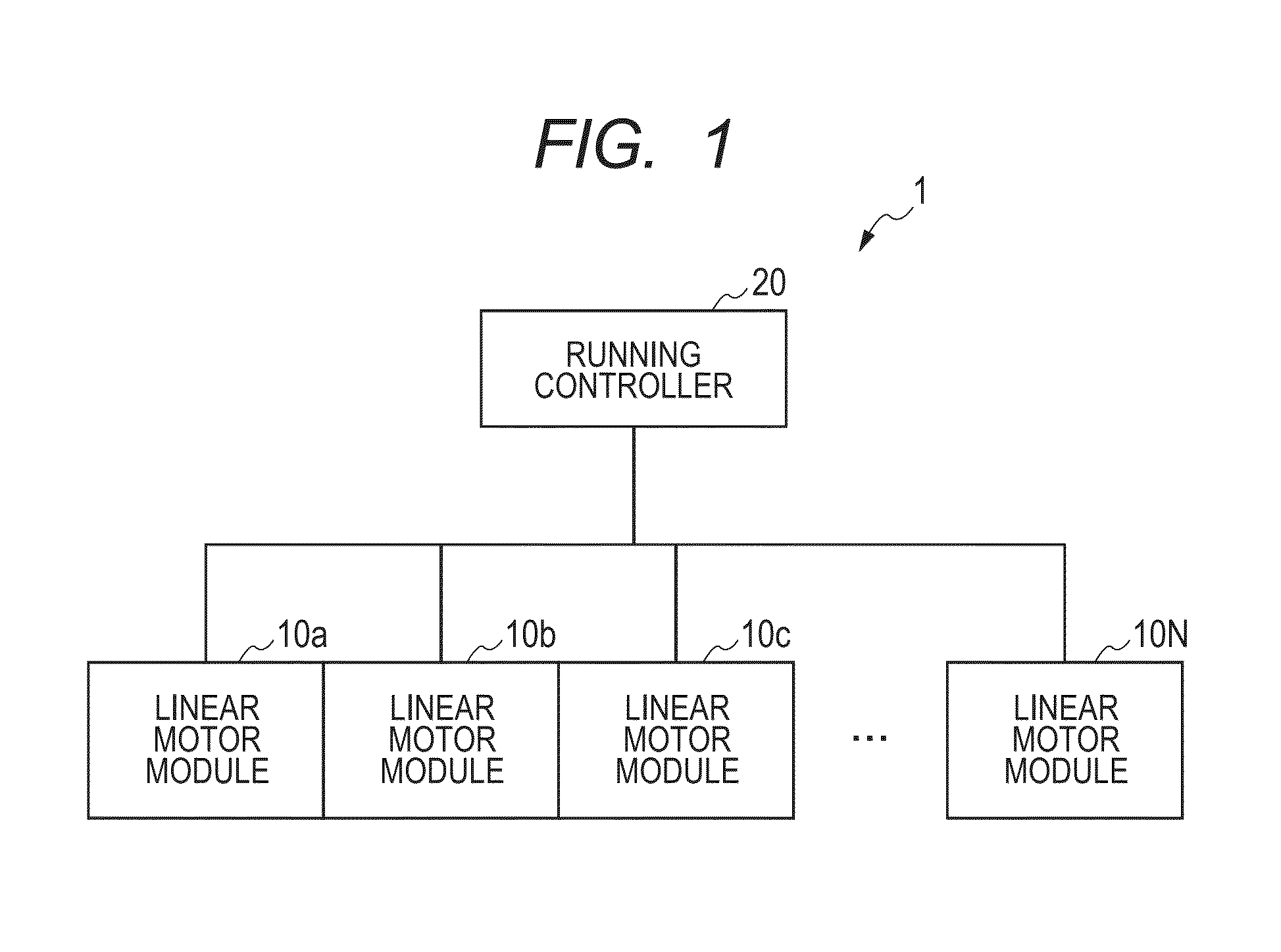
[0042]The first embodiment of the invention will be described hereinbelow with reference to the drawings. FIG. 1 is a schematic constructional diagram of a linear motor control system 1 according to the first embodiment of the invention. As illustrated in FIG. 1, the linear motor control system 1 has: linear motor modules 10a to 10N serving as linear motor control apparatuses; and a running controller 20 serving as a running control unit. The linear motor control system 1 is a moving magnet type linear motor. In the embodiment, for example, the linear motor control system 1 has the N (N is an integer of 2 or more) linear motor modules 10a to 10N.

[0043]The linear motor modules 10a to 10N are continuously arranged and construct one conveying path. Trucks which move in the linear motor control system 1 are controlled by the linear motor modules 10a to 10N and move or stop on the conveying path.

[0044]The running controller 20 controls the linear motor modules 10a to 10N. When describing...

second embodiment

[0104]A linear motor control system according to the second embodiment of the invention will be described hereinbelow. The second embodiment differs from the first embodiment with respect to a point that, in the linear motor module, a combination as motor controllers is abandoned and a control deviation information selector is provided in place of the current information selector. Other construction is common. Therefore, the same component elements as those in the first embodiment are designated by the same reference numerals and their description is omitted here.

[0105]FIG. 8 is a schematic constructional diagram of the linear motor module 100a according to the second embodiment of the invention. As illustrated in FIG. 8, control deviation calculators 181 to 183 are connected to a control deviation information selector 184 as a switching unit. The control deviation information selector 184 is connected to position controllers 191 to 194. The position controllers 191 to 194 are conne...

third embodiment

[0142]A manufacturing system 800 of articles according to the third embodiment of the invention will be described with reference to FIG. 13. The manufacturing system 800 of articles has: the linear motor control system 1 according to the first embodiment; processing apparatuses 810 and 811; and a process controller 820. The linear motor control system 1 conveys a work 801 between the processing apparatuses 810 and 811. In this instance, the articles denote, for example, a toner cartridge for an ink jet printer or a copying apparatus, parts for a camera, semiconductor products, and the like. The process controller 820 collects process information of the processing apparatuses 810 and 811 and forms a conveying process of the truck. The number of processing apparatuses 810 and 811 is not limited to two.

[0143]A manufacturing method of articles by the manufacturing system 800 will be described. The running controller 20 transmits group conveying commands to the motor controller 130 in a ...


PUM


Abstract

A linear motor control apparatus has: a plurality of coil units; a plurality of position detecting units for detecting positions of a plurality of trucks which move over the plurality of coil units; a plurality of deviation calculating units for operating deviation information as differences between the detected truck positions and a target position of the detected truck; a plurality of position control units for operating current control signals based on the deviation information; a plurality of current control units for supplying driving currents to the coil units based on the current control signals; and a switching unit for switching the position control units to which the deviation information is transmitted or switching the current control units to which the current control signals are transmitted.

Description

BACKGROUND OF THE INVENTION[0001]1. Field of the Invention[0002]The present invention relates to a linear motor and, more particularly, to a linear motor control apparatus of a linear motor of a moving magnet type and a linear motor control system.[0003]2. Description of the Related Art[0004]A linear motor of a moving magnet type has such a construction that a magnet is arranged in a truck serving as a needle and a coil is arranged in a stator, respectively, and is suitable for conveyance of a long stroke as compared with a linear motor of a moving coil type in which an electric wire is connected to a truck. In such a moving magnet type linear motor, when a driving stroke longer than a size of needle is necessary, a plurality of coils corresponding to a stroke length are necessary. Generally, the moving magnet type linear motor has such a construction that a plurality of coils are arranged and connected to a current controller so that current control by three phases can be made (ref...

Claims


Application Information

Patent Timeline
IPC IPC(8): H02P6/00H02P25/06B65G35/06
CPCH02P6/006H02P25/06B65G35/06B65G54/02H02P6/16H02P6/28
Inventor SUZUKI, NORIHIROYAMAMOTO, TAKESHITOMODA, KOJIDEGUCHI, SATORUNARAHARA, HIDETADA
Owner CANON KK
Why Eureka
Try Eureka