
Variable Resolution Eye Mounted Displays

a display and variable resolution technology, applied in the field of visual display technology, can solve the problems of limiting the scale of information and context available, increasing power requirements as well as costs, and limiting the convergence of physical display size,

Active Publication Date: 2015-10-29
TECTUS CORP
View PDF1 Cites 155 Cited by
  • Summary
  • Abstract
  • Description
  • Claims
  • Application Information

AI Technical Summary

Benefits of technology

The patent text describes a method for improving the image quality of optical systems by using a curved surface to correct astigmatism. The method involves using a display mesh as an internal skeleton to stiffen the bulk contact lens, which prevents it from bending to conform to the shape of the cornea. This helps to preserve the outer side shape of the lens and bypasses astigmatism errors caused by the corneal surface. The method can be applied to both cameras and displays, and it improves image quality by reducing astigmatism and other optical aberrations.

Problems solved by technology

Restrictions in size limit the possible field of view, which limits not just the resolution but scale of information and context available.
Larger physical display sizes alleviate such limits, but rule out portability, and increases power requirements as well as cost.
While there is some convergence in devices, e.g. smartphones are commonly used instead of dedicated small digital cameras, physical display size currently limits how far such convergence can go.
However, the current crop of display technologies makes a number of tradeoffs between these goals in order to satisfy a particular market segment.
For example, direct view color CRTs do not allow direct addressing of individual pixels.
Direct view LCD panels have generally replaced CRTs in most computer display and TV display markets, but at the trade-offs of temporal lag in sequences of images, lower color quality, lower contrast, and limitations on viewing angles.
Display devices with resolutions higher than the 1920×1024 HDTV standards are now available, but at substantially higher cost.
Projection display devices can now produce large, bright images, but at substantial costs in lamps and power consumption.
Displays for cell phones, tablets, handheld games, small still and video cameras, etc., must currently seriously compromise resolution and field of view.
Within the specialized market where head mounted displays are used, there are still serious limitations in resolution, field of view, undo warping distortion of images, weight, portability, cosmetic acceptability, and cost.
All these approaches have much higher costs when higher light output is desired, as is necessary when larger display surfaces are desired, when wider useable viewing angles are desired, for stereo display support, etc.
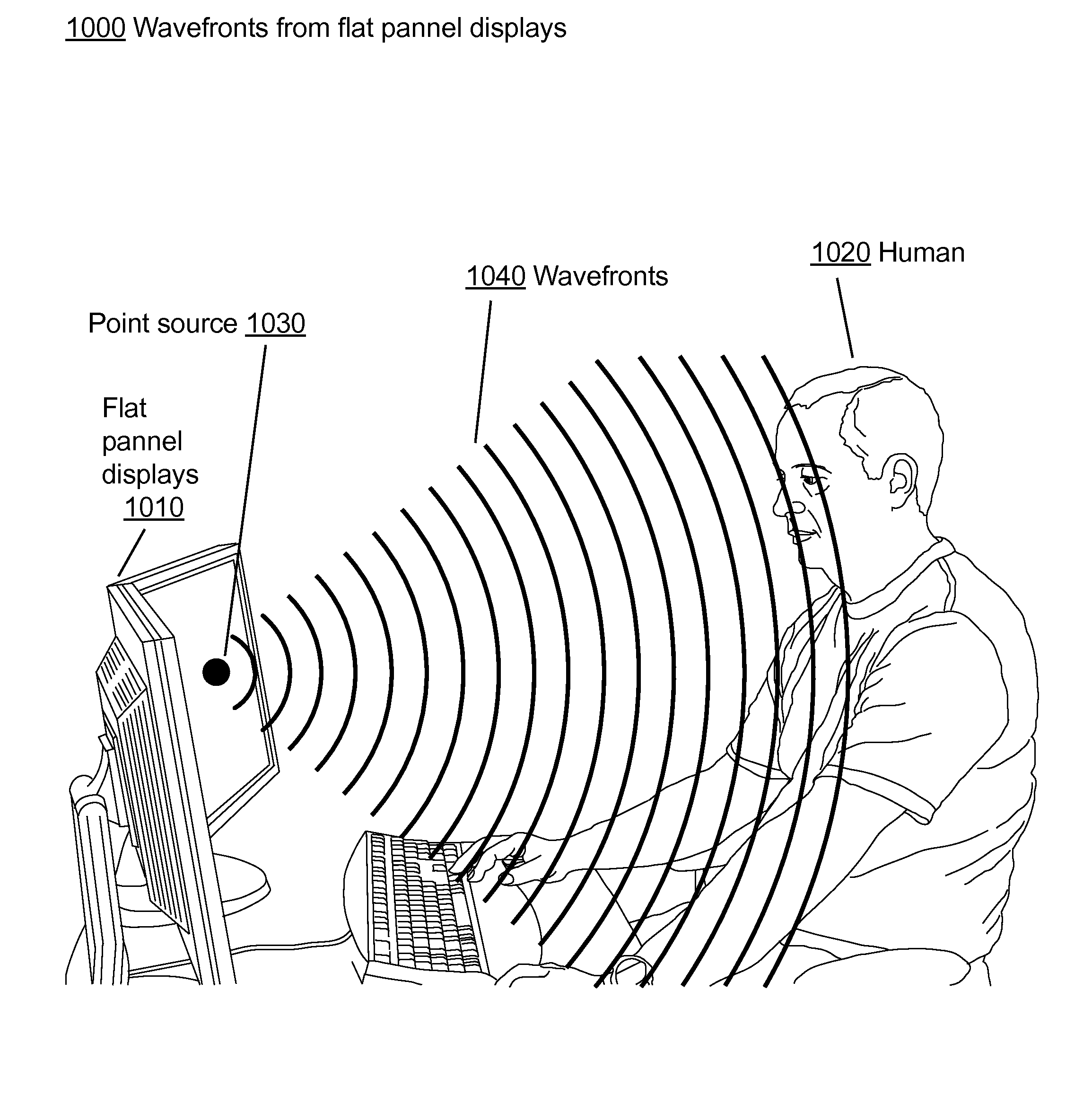
Another general problem with current direct view display technology is that they are all inherently limited in the perceivable resolution and field of view that they can provide when embedded in small portable electronics products.
Larger, higher resolution direct view displays are bulky enough that they must remain in the same physical location day to day (e.g., large plasma, LCD, or OLED display devices).
One problem with current rear projection display technologies is that they tend to come in very heavy bulky cases to hold folding mirrors.
One problem with current front projection display technology is that they take time to set up, usually need a large external screen, and while some are small enough to be considered portable, the weight savings comes at the price of color quality, resolution, and maximum brightness.
Many also have substantial noise generated by their cooling fans.
Current head mounted display technology have limitations with respect to resolution, field of view, image linearity, weight, portability, and cost.
While there have been many innovative optical designs for head mounted displays, controlling the light from the native display to the device's exit pupil can result in bulky, heavy optical designs, and rarely can see-through capabilities (for augmented reality applications, etc.) be achieved.

Method used


Image

  • Variable Resolution Eye Mounted Displays
  • Variable Resolution Eye Mounted Displays
  • Variable Resolution Eye Mounted Displays

Examples


Embodiment Construction

Outline

[0108]I. Overview

[0109]II. Anatomical and Visual Definitions[0110]II.A. Terminology[0111]II.B. Retinal Definitions[0112]II.C. Axis: Classical Optical vs. the Human Eye[0113]II.D. Important Retinal Neural Cell Types

[0114]III. Mathematical Definitions[0115]III.A. Mathematical Conventions[0116]III.B. Hexagonimania[0117]III.C. Mathematical Definitions of the ViewSphere and Related Concepts[0118]III.D. Scale Changes between the ScreenSurface and ViewSpaceVS[0119]III.E. Re-Definition of Resolution

[0120]IV. The Variable Resolution Nature of the Human Eye

[0121]V. Optical Function Required for Eye Mounted Displays

[0122]VI. Optical Function of a Contact Lens Display

[0123]VII. Variable Resolution Mappings for Contact Lens Displays

[0124]VIII. Means to Display Variable Resolution Pixels[0125]VIII.A. Pixel Tilings Overview[0126]VIII.B. Projector Tilings[0127]VIII.C. Pixel Tilings Details[0128]VIII.D. Sub-Sampling of Color for an Eye Mounted Display[0129]VIII.E. Computer Graphics Real-Time ...


PUM


Abstract

A display device (e.g., in a contact lens) is mounted on the eye. The eye mounted display contains multiple sub-displays, each of which projects light to different retinal positions within a portion of the retina corresponding to the sub-display. Additionally, a “locally uniform resolution” mapping may be used to model the variable resolution of the eye. Accordingly, various aspects of the display device may be based on the locally uniform resolution mapping. For example, the light emitted from the sub-displays may be based on the locally uniform resolution mapping.

Description

CROSS-REFERENCE TO RELATED APPLICATIONS[0001]This application claims the benefit of U.S. Provisional Application No. 61 / 924,924, filed Jan. 8, 2014, which is incorporated by reference in its entirety.[0002]This application relates to U.S. patent application Ser. No. 12 / 359,211, “Eye Mounted Displays,” by Michael Deering and Alan Huang, filed on Jan. 23, 2009, and U.S. patent application Ser. No. 12 / 359,951, “Systems Using Eye Mounted Displays,” by Michael Deering, filed on Jan. 26, 2009. The subject matter of all of the foregoing is incorporated herein by reference in their entirety.BACKGROUND OF THE INVENTION[0003]1. Field of the Invention[0004]This invention relates generally to visual display technology. More particularly, it relates to display technology for eye mounted display, and specifically to contact lens displays.[0005]2. Description of the Related Art[0006]More and more our technological society relies on visual display technology for work, home, and on-the-go use: docum...

Claims


Application Information

Patent Timeline
Patent Type & Authority Applications(United States)
IPC IPC(8): H04N13/04G02B27/00A61F2/16G09G3/02H04N9/31G02B27/01G06F3/01
CPCH04N13/044G02B2027/0138G02B27/0093G06F3/013H04N13/0484G06F3/012G09G3/02H04N9/3129H04N9/3197A61F2/1602A61F2/1613G02B2027/0187G02B2027/0134G02B2027/0147G02B27/0172G02B13/0085G02B13/16G02C7/04G02B2027/0196G09G3/001
Inventor DEERING, MICHAEL FRANKHUANG, ALAN
Owner TECTUS CORP
Learn More