Material used in the removal of contaminants from liquid matrices
a technology of liquid matrices and contaminants, applied in the direction of physical/chemical process catalysts, mechanical vibration separation, metal/metal-oxide/metal-hydroxide catalysts, etc., can solve the problems of inability to control the morphology of synthesized oxides, high cost of wastewater removal technology, and secondary pollutants, etc., to achieve high mechanical resistance and reusable
- Summary
- Abstract
- Description
- Claims
- Application Information
AI Technical Summary
Benefits of technology
Problems solved by technology
Method used
Image

Examples
example 1
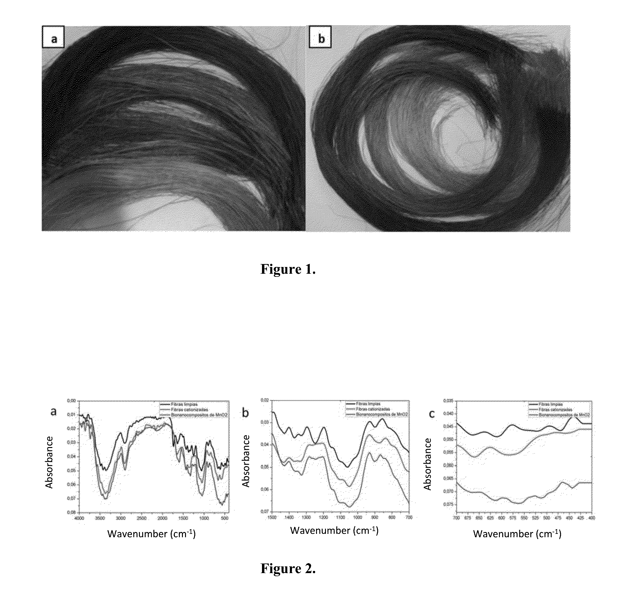
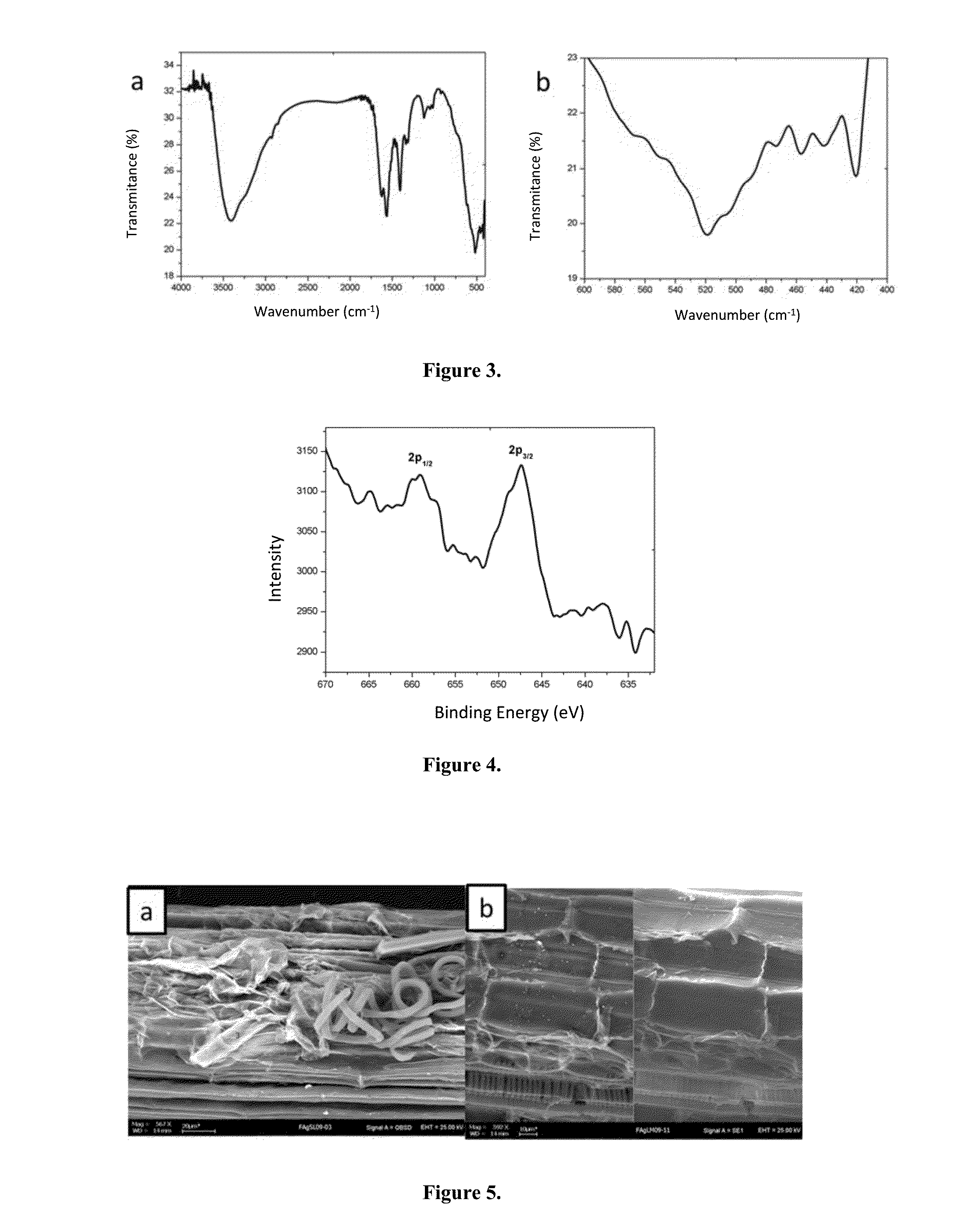
Synthesis and Production In Situ of Nanoparticles of Mn3O4 on Fique Fibers
[0051]Steps followed to modify the electrostatic environment of fique fibers. The starting material was prepared by:[0052]a) Immersing clean fique fibers in an aqueous solution of HCl, 6% on weight;[0053]b) Transferring fique fibers to an aqueous solution of NaOH, 6% on weight;[0054]c) Drying fibers at 60° C. for 15 hours.
[0055]Modified fique fibers were submerged in a precursor solution of MnSO4H2O 5 mM. The solution was irradiated with Ultrasound (20 to 40 kHz, 130W) during 25 minutes. Then fibers were transferred to an aqueous solution of NH4OH at 85° C. during 1 hour. Finally the resulting material was dried at 100° C. under an oxidizing atmosphere. Several precursor solutions were used, for example: 0.5, 1.0, 5.0, 30.0 and 100.0 mM. Likewise, the immersion times of fibers in precursor solution was also varied from 12.5 to 50 minutes. To achieve a concentration of MnSO4H2O 5 mM the stoichiometric amounts o...
example 2
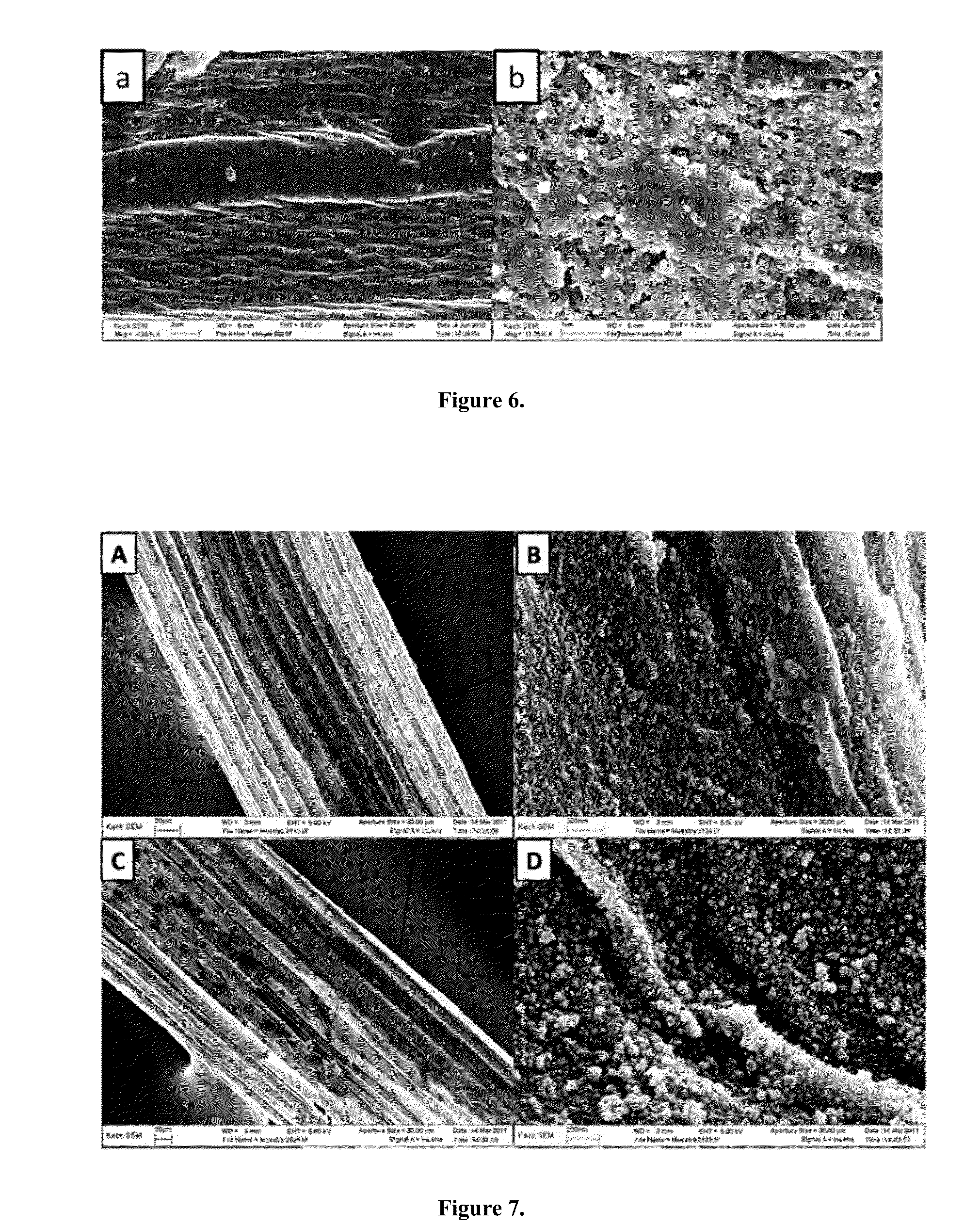
Synthesis In Situ of MnO2 Nanoparticles on the Surface of the Fique Fibers
[0056]Electrostatic environment modification of fique fibers was achieved by cationizing. To cationize their surface fique fibers were submerged in an aqueous solution of HCl 5% wt for 3 hours at room temperature. Then fibers were washed in abundant water, followed by immersion in a solution of NaOH 6% wt for 3 hours at 60° C. Finally fibers were dried at 80° C.
[0057]Nanoparticles synthesis was achieved by immersing the modified fibers in a solution of KMnO4 5 mM for 40 minutes. The fiber set of fique fibers-KMnO4 solution was irradiated with ultrasound (between 20 to 40 kHz, 130W), during immersion time. Finally, fibers were removed from solution and dried at 60° C. overnight. The concentration of precursor solution was varied, 2, 5, 10, 30 and 100 mM concentrations were tested.
example 3
Synthesis In Situ of MnO2 Nanoparticles on the Surface of the Fique Fibers
[0058]This method is a variation of the synthesis method from Example 2. This method consisted to immersing the fique fibers in a precursor solution of KMnO4 during 30 minutes; followed by the addition of 20 mL of ethanol (Analytical grade) under constant stirring; reaction mixture is allowed to reach equilibrium during 2 hours. Finally the modifies fiber were dried at 60° C.
PUM
| Property | Measurement | Unit |
|---|---|---|
| Size distribution | aaaaa | aaaaa |
| Size distribution | aaaaa | aaaaa |
| Frequency | aaaaa | aaaaa |
Abstract
Description
Claims
Application Information
 - R&D
- Intellectual Property
- Life Sciences
- Materials
- Tech Scout
- Unparalleled Data Quality
- Higher Quality Content
- 60% Fewer Hallucinations
Browse by: Latest US Patents, China's latest patents, Technical Efficacy Thesaurus, Application Domain, Technology Topic, Popular Technical Reports.
© 2025 PatSnap. All rights reserved.Legal|Privacy policy|Modern Slavery Act Transparency Statement|Sitemap|About US| Contact US: help@patsnap.com