

Methods of making optical fiber with reduced hydrogen sensitivity
- Summary
- Abstract
- Description
- Claims
- Application Information
AI Technical Summary
Benefits of technology
Problems solved by technology
Method used
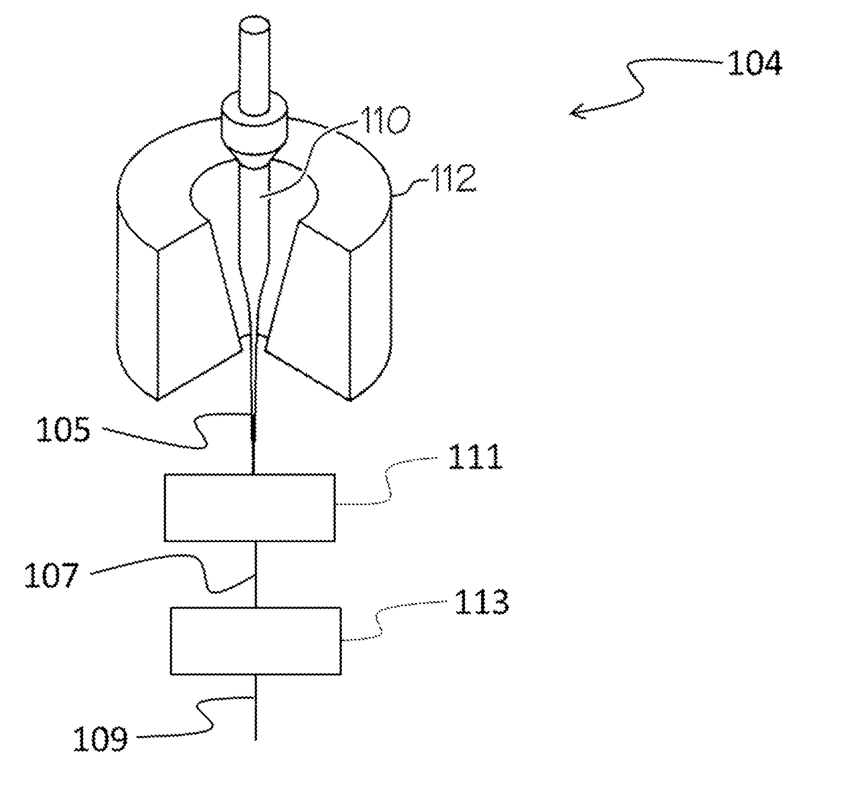
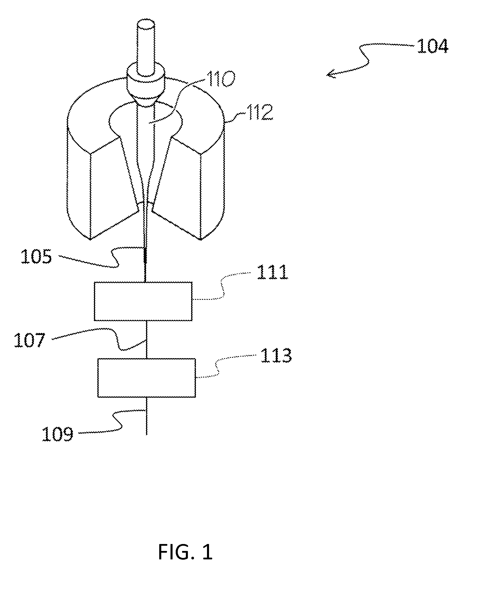
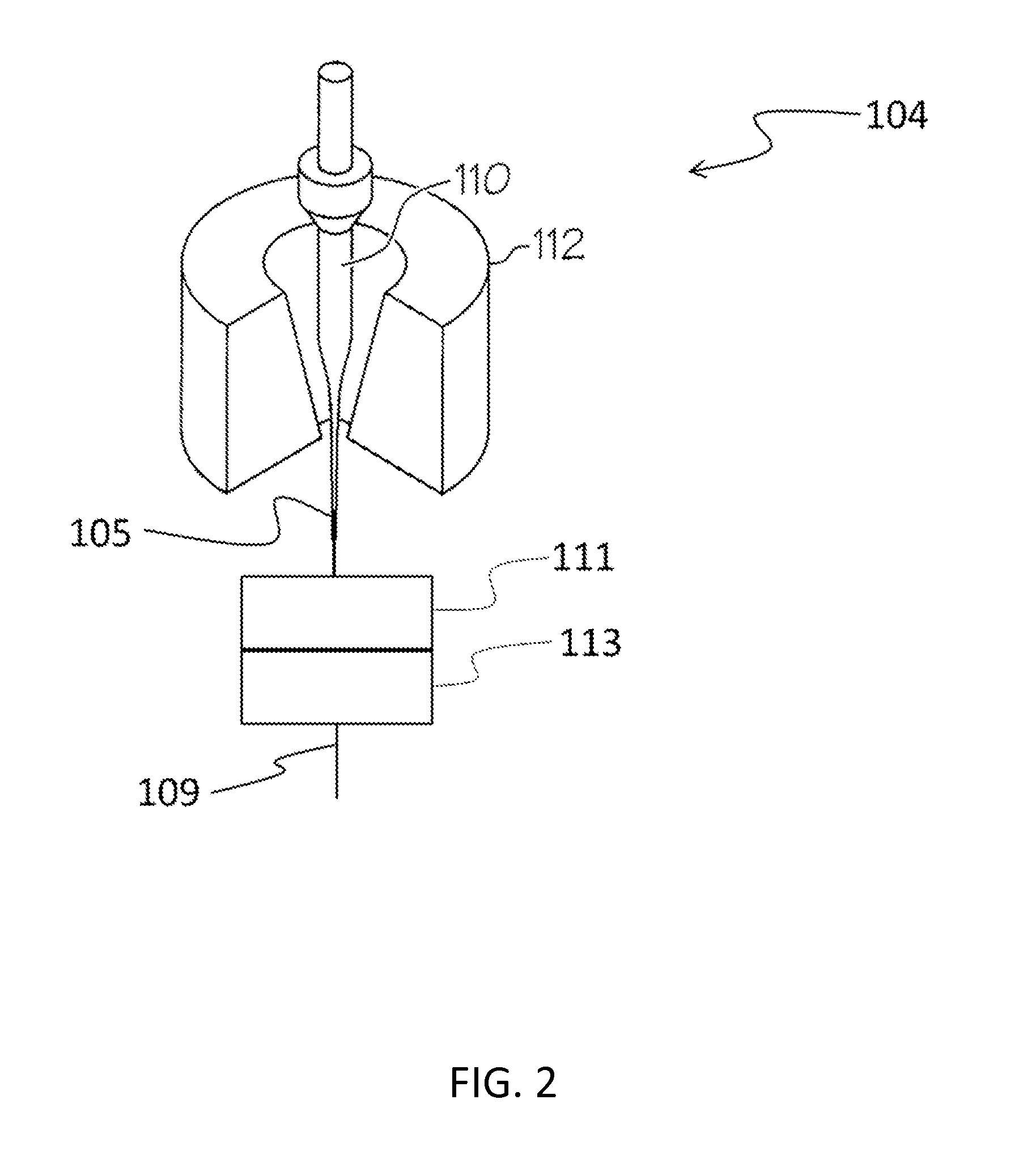
Image

Examples
example 1
[0074]A series of six fibers was prepared under various treatment conditions to demonstrate the reduction in non-bridging oxygen defects provided by the methods of the present disclosure. Fibers were drawn from a single mode silica preform comprised of germania-doped core. The preform was heated to a draw temperature above 2000° C. in a drawing furnace in a vertical direction and transported to a series of two downstream treatment regions. The first treatment region included a heated zone maintained at 1200° C. The entrance average temperature of the fibers into the first treatment region was ˜1580° C. and the average temperature of the fibers exiting the first treatment region was in the range 1300° C.-1330° C. Fiber samples 1, 2, and 3 were cooled in the first treatment region at a rate of about 2500° C. / s and had a residence time in the first treatment region of about 0.20 sec. Fiber samples 4, 5, and 6 were cooled in the first treatment region at a rate of about 2850° C. / s and h...
example 2
[0077]In this example, fibers prepared using different cooling profiles are compared. The fibers were drawn in separate trials from the same apparatus and subjected to one of the two cooling profiles illustrated in FIG. 4. Each cooling profile in FIG. 4 shows the fiber surface temperature as a function of time, where a time of zero corresponds to the point in time at which the fiber has an average temperature of 1700° C. Cooling profile 1 represents a profile consistent with prior art fiber processing conditions, while cooling profile 2 represents a profile in accordance with the present disclosure.
[0078]For cooling profile 1, the fibers entered the first treatment region with an average fiber temperature of 1700° C., were cooled at an average rate of 7500° C. / s, and exited the first treatment region with an average fiber temperature of 1400° C. The fibers then entered a second treatment region with an average fiber temperature of 1400° C., were cooled at an average rate of 15,000° ...
example 3
[0081]In this example, the effect of the temperature of the heated region of the first treatment region on the non-bridging oxygen defect concentration of a series of seven fibers was considered. The fibers were prepared from a common optical fiber preform in a common drawing apparatus that included a drawing furnace, a first treatment region downstream from the drawing furnace, a second treatment region downstream from the first treatment region, and drawing mechanism. The second treatment region was directly adjacent the first treatment region and consisted of cooling the fiber in air. After exiting the first treatment region, each fiber was cooled in air in the second treatment region for the same residence time and then quenched. After quenching, the non-bridging oxygen defect concentration was measured.
[0082]The temperature of the heated zone of the first treatment region impacts the fiber temperature-time history in the first treatment region as well as the exit temperature of...
PUM
| Property | Measurement | Unit |
|---|---|---|
| Temperature | aaaaa | aaaaa |
| Temperature | aaaaa | aaaaa |
| Temperature | aaaaa | aaaaa |
Abstract
Description
Claims
Application Information