
Auxiliary resonant commutated pole converter with voltage balancing circuit

a voltage balancing circuit and auxiliary resonant technology, applied in the field of improvement, can solve the problems of increasing frequency, reducing life span, and reducing the characteristics of none of the components, and reducing the life span

Active Publication Date: 2015-11-05
COMSYS
View PDF2 Cites 9 Cited by
  • Summary
  • Abstract
  • Description
  • Claims
  • Application Information

AI Technical Summary

Benefits of technology

The patent text explains that balancing the DC power source in a resonant power converter can reduce the voltage across switches, leading to lower losses during switching. This is particularly beneficial in an active filter application where the voltage / current error may change quickly. By balancing the DC power source, the power converter can switch against significant voltages without being affected by the error. In summary, the patent text describes a technical solution for improving the performance of resonant power converters in various applications.

Problems solved by technology

In power converters, losses appear as none of the components have ideal characteristics.
The losses introduce heat in the power circuitry, which apart from consuming energy introduces thermal strain to all components, reducing the life span.
However, increasing the frequency also increases switching losses, as most losses appear on switching cycle basis.
Thus, reducing the current through the semiconductor or the voltage thereover reduces the total power input for the switch and thus the total power input to the system.
In applications where the converter or inverter is connected directly to the grid, EMI noise can cause problems which are normally solved by employing EMC-filters.

Method used


Image

  • Auxiliary resonant commutated pole converter with voltage balancing circuit
  • Auxiliary resonant commutated pole converter with voltage balancing circuit
  • Auxiliary resonant commutated pole converter with voltage balancing circuit

Examples


Embodiment Construction

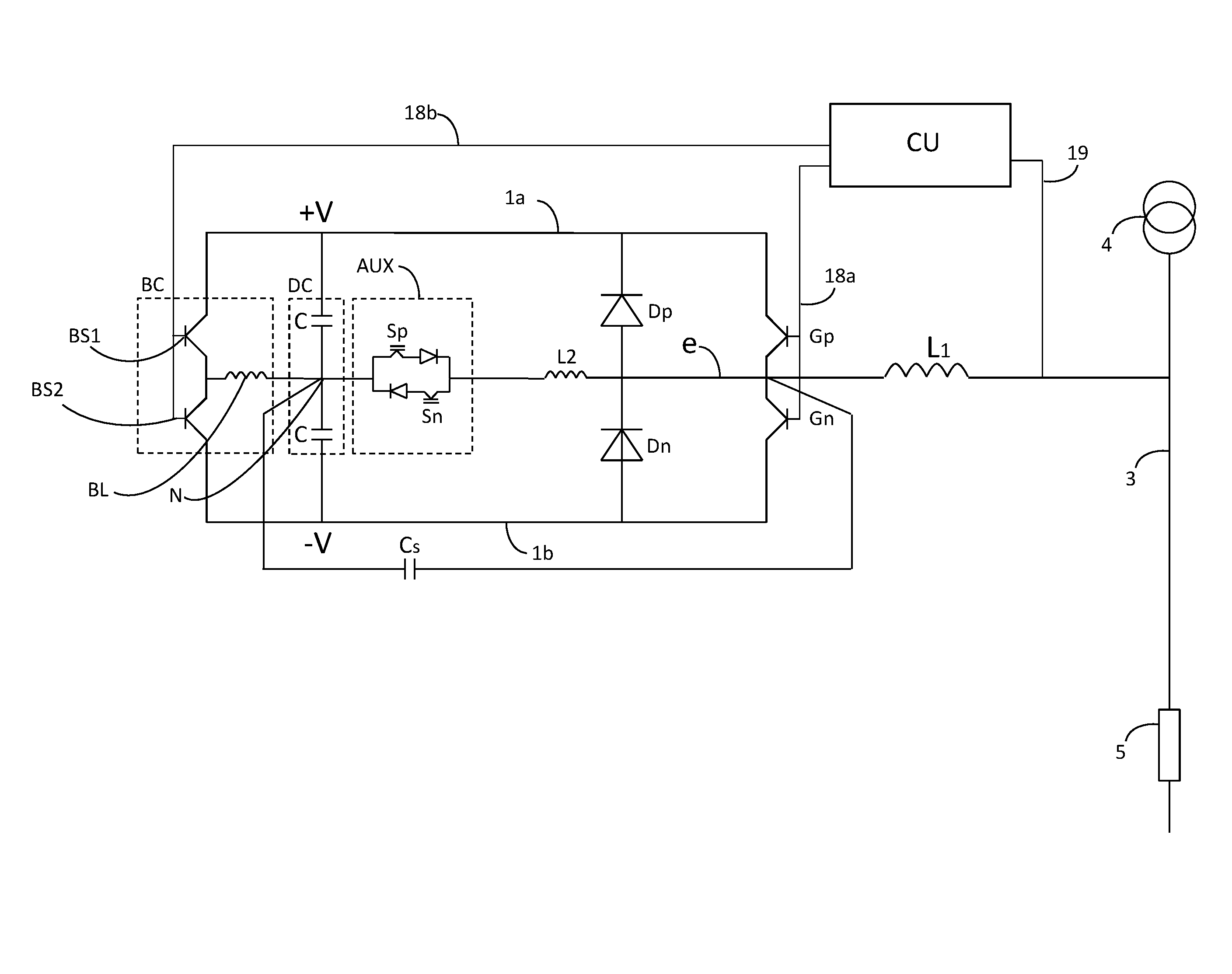
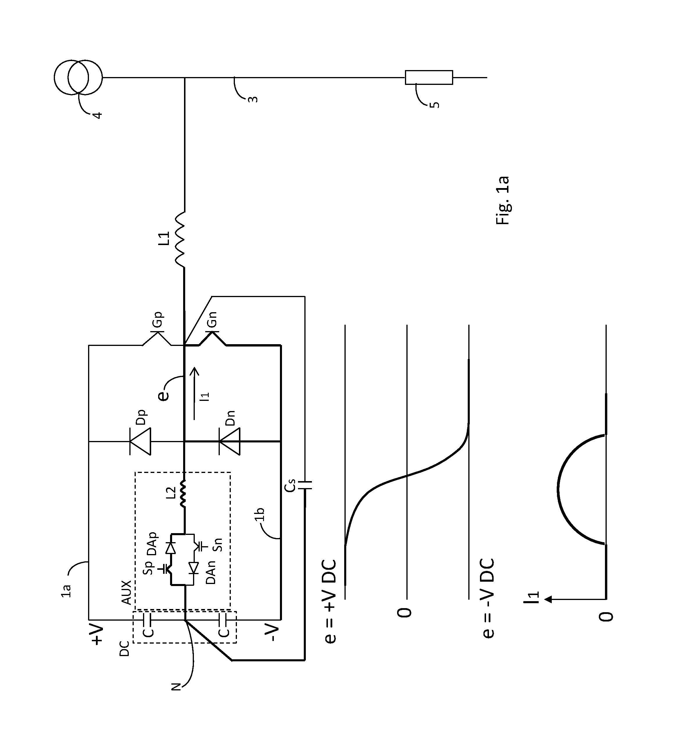
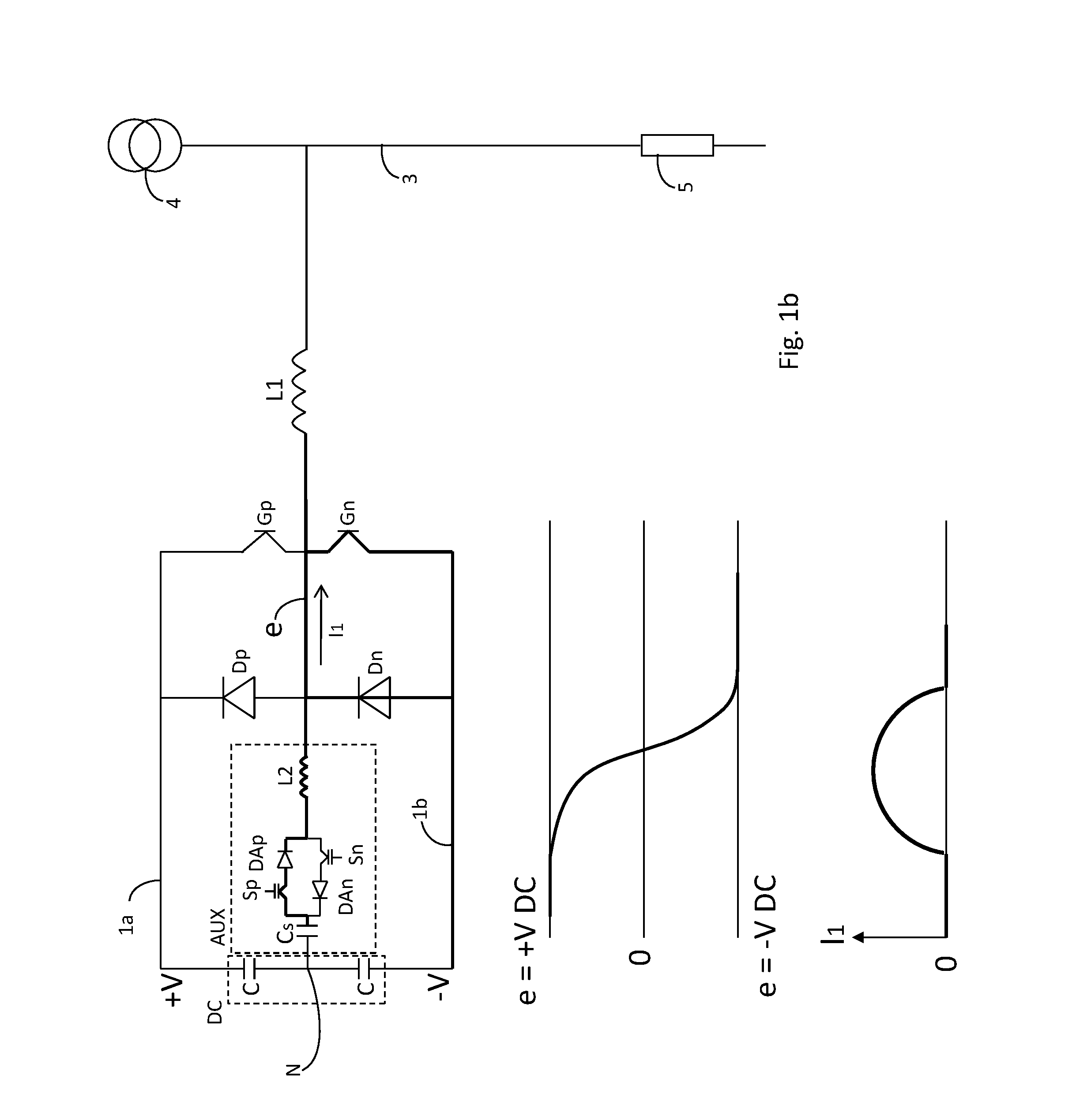
[0027]The fundamentals of a power converter using resonant power conversion, or switching, will now be described by means of an example, under reference to the accompanying drawings. It will be appreciated that the drawings are for illustration only and are not in any way restricting the scope.

[0028]In the following figures, the power converter is illustrated for use in an active filter. However, this embodiment is only to be seen as an example of one use of the power converter. The inventive concept defined by the appended claims could be used in all applications in which a resonant power converter is needed, such as for example in a power transformer.

[0029]The power converter in an active filter creates a compensating current which compensates for loads in an electrical system creating harmonics. By reducing the harmonics in the electrical system, disturbances are reduced and losses in the electrical system are reduced. A further description of the details of an active filter coul...


PUM


Abstract

A resonant power converter is provided. The resonant power converter comprises a balancing circuit for balancing the voltage in a feeding connection. The balancing circuit comprises: a first positive control means in series with an inductor, wherein the first positive control means and the inductor is coupled between the positive DC conductor and the feeding connection, and a second negative control means in series with the inductor, wherein the second negative control means are coupled between the negative DC conductor and the feeding connection. The first positive and second negative control means are adapted to be alternatingly switched on and off for balancing the resonant power converter, such that the voltage in the feeding connection is substantially the mean voltage of the positive DC conductor and the negative DC conductor.

Description

TECHNICAL FIELD[0001]The invention generally relates to an improved circuit for resonant power conversion limiting the power required for switching.BACKGROUND[0002]In power converters, losses appear as none of the components have ideal characteristics. The losses introduce heat in the power circuitry, which apart from consuming energy introduces thermal strain to all components, reducing the life span.[0003]It is desirable to increase the frequency of operation of power converters as the generated output then can be more exactly controlled. Increasing the switching frequency leads to lower switching ripple, smaller component values which in turn leads to a more compact, light-weight and cost-effective implementation of the invention. Further, lower switch ripple allows for potentially lowered EMI, which in turn goes closer to the goal of a non-disturbing switch. Still further, having a high switching frequency allows for higher frequency currents to be generated by the power convert...

Claims


Application Information

Patent Timeline
IPC IPC(8): H02M7/537H03H11/32H02M1/12H02M1/00H02M7/48H02M7/5387
CPCH02M7/537H02M2007/4811H03H11/32H02M1/12H02M7/5387H02M3/156Y02B70/10H02M1/0058H02M7/4811H02M7/4815H02M7/4807H02M7/487H02M7/5236
Inventor HANSSON, ERIK
Owner COMSYS
Learn More