Low elasticity films for microfluidic use

a microfluidic and low-elasticity technology, applied in the field of diaphragm technology, to achieve the effect of improving efficiency and speed of operation

Active Publication Date: 2015-11-12
PERKINELMER HEALTH SCIENCES INC
View PDF7 Cites 39 Cited by
  • Summary
  • Abstract
  • Description
  • Claims
  • Application Information

AI Technical Summary

Benefits of technology

[0022]To improve the efficiency and speed of operation of a microfluidic circuit element such as a valve or a pump, it is desirable that the work required to change from a first state to a second state is minimal. A preferred class of circuit elements is diaphragm operated. The pneumatically controlled diaphragm separates a pneumatic subcavity from a hydraulic subcavity and operates on a fluid contained in the hydraulic subcavity. The diaphragm “web” is a thin film that serves as a barrier between the two subcavities, dynamically translating pneumatic pressure into fluid motion, or stasis. In a first state, the diaphragm web is in a first position between the subcavities, in a second state the diaphragm web is displaced from the first position and occupies a second position. Generally the first position conforms proximately to an interior surface of the hydraulic subcavity and the second position conforms proximately to a second interior surface of the pneumatic subcavity, and by exerting a force, the diaphragm may be reversibly transitioned between the two positions or states.
[0024]It is desirable for the web for use in these microfluidic cartridges be a film that is not significantly elastomeric and generally matches the interior surface area of one subcavity the target microcavity, preferably the interior surface area of the larger subcavity of the microcavity. Most preferably, the film requires little or no work to transition from one state to another. The film is desirably in a flaccid state until the applied control pressure drives the film to one side or the other of a microfluidic cavity by inverting the film position. Preferably, the film can also be described as having near zero or zero restorative force toward a reduced area state. Most preferably, the film is a low or non-elastomeric film that does not significantly self-restore to a form with a surface area approximating the cross-sectional area of the cavity, and substantially matches the interior surface area of the subcavities without significant over or under pressure. Using a non-elastomeric film with a surface area matching the interior surface enables several advantageous and novel properties.
[0025]The use of low or non-elastomeric films as microfluidic components enables the production of valves, pumps and microfluidic features that have advantageous features. Notably through the use of low or non-elastomeric films, the restoring force of an elastomeric film does not need to be overcome as the film is moved from one side of the microcavity to the other. This reduction in force arises because the pneumatic control needs only overcome the inertia of the membrane and fluid, not the elastic spring force of the film plus the inertia of the membrane and fluid. This enables a faster cycling and / or cycling with reduced pressure, or both, of the membrane between one side and the other, e.g. from the open state to the closed state for a valve.Manufacture
[0029]The film can also be yielded prior to assembly. In this case, the assembly process needs to gather sufficient non-elastomeric film to line the surface area of the desired target cavity. This can be accomplished through the use of a punch and die combination, or by vacuum or pressure forming the film into a die, wherein the die has dimensions similar to the target microcavity. The film can then be positioned on the microfluidic subassembly and the non-elastomeric film transferred by a suitable change in pressure. Those skilled in the art can recognize that it may be advantageous to insert manufacturing steps in the process, such as transferring the film and a perimeter to an adhesive layer, bonding the ungathered film with heat, pressure, or solvent, applying adhesive to the ungathered material, cutting a perimeter to create a bondable area for the yielded film, or combinations thereof. When the film is yielded prior to cartridge assembly, manufacturing conditions that might be harmful to the microfluidic chip may be used. Specifically, it may be desirable for manufacturing reasons to use either pressure or thermal processing steps that may be incompatible with the microfluidic assembly, or reagents therein. By performing the yield process off of the microfluidic assembly, it becomes possible to use combinations of pressure and temperature that are relatively inaccessible to an assembled chip. This permits the use of polymers such as polyimide that have optimal process conditions that exceed the strength, and or desired temperatures desirable for plastic microfluidic cartridges. By utilizing these manufacturing techniques, those skilled in the art will appreciate greater flexibility microfluidic cartridge design and manufacture.
[0030]In all cases, it is desirable that the film be stretched sufficiently to irreversibly yield the material. Specifically, the stretch applied should exceed the yield point of the film to create non-elastomeric or very low elasticity film such that the yielded film has a surface area and shape complimentary to the inner surface of the microfluidic cavity into which it is assembled. It is known in the art that not all microfluidic cavities are symmetric with respect to the film layer, and in these cases, it may desirable that the surface area of the film match the larger of the two microcavities for most uses. For some uses, it may be sufficient to have the film match the surface area of the hydraulic or pneumatic side only. For example, it may be desirable with several microcavities in sequence to have the operating volume change be different amongst the microcavities. This can be readily accomplished by having an asymmetric division of the microcavity by the film.

Problems solved by technology

Unfortunately, currently existing microfluidic diaphragms are generally elastomeric in nature and require overcoming the significant elastomeric resistance to change from a first state to a second state.

Method used


Image

  • Low elasticity films for microfluidic use
  • Low elasticity films for microfluidic use
  • Low elasticity films for microfluidic use

Examples


Embodiment Construction

[0066]Although the following detailed description contains specific details for the purposes of illustration, one of skill in the art will appreciate that many variations and alterations to the following details are within the scope of the claimed invention. The following definitions are set forth as an aid in explaining the invention as claimed.

DEFINITIONS

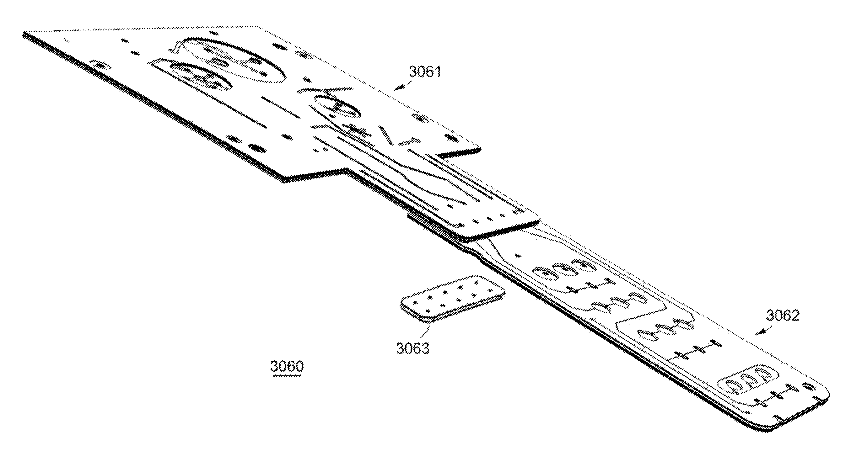
[0067]A “cartridge” is an analytical device designed for operation by insertion into a host instrument. The host instrument supplies the pneumatic pressure, pulses, and detection means for performance of the assay. The cartridge contains hydraulic works and pneumatic works, including microscale channels, cavities and chambers. Sample and reagent liquids are conveyed in a hydraulic network of the cartridge or card; fluid flow is controlled and driven by a pneumatic network that interfaces with the hydraulics at diaphragms spanning selected junctions, channels and chambers. Typically, the body of the cartridge or card is made of a f...


PUM

PropertyMeasurementUnit
Young's modulusaaaaaaaaaa
elasticityaaaaaaaaaa
surface areaaaaaaaaaaa

Abstract

Microfluidic circuit elements, such as a microvalve, micropump or microvent, formed of a microcavity divided by a diaphragm web into a first subcavity bounded by a first internal wall and a second subcavity bounded by a second internal wall, where the diaphragm web is characterized as a thin film having a first state contacting the first internal wall and a second state contacting the second internal wall and exhibiting essentially no elasticity in moving between the first state and the second state, the thin film web having been stretched beyond its yield point before or during use are provided. The disclosed elements enable faster and more efficient cycling of the diaphragm in the microcavity and increases the diaphragm surface area. In a preferred embodiment, the microfluidic circuit element is pneumatically driven and controls the motion of fluids in a microassay device.

Description

BACKGROUND[0001]1. Technical Field[0002]This disclosure is generally directed to diaphragm technologies for microvalves, micropumps and other pneumatic fluidic elements for use in microassay devices, and to their methods of manufacture.[0003]2. Description of the Related Art[0004]Microassay cartridges have found increasing use as devices for diagnostic assays. The devices described by Wilding in U.S. Pat. No. 5,304,487 consisted of “mesoscale” channels and chambers formed on reusable silicon substrates that were infused with fluid reagents from off-cartridge syringe pumps. Little consideration was given to on-board fluid handling and control. However, practical commercial applications have led in the direction of “consumable” cartridges—disposable, single use “sample-to-answer” cartridges that are self-contained for all reagents needed for a particular assay or panel of assays.[0005]Microscale means for handling fluids include mechanical hydraulic systems such as piston driven devic...

Claims


Application Information

Patent Timeline
Patent Type & Authority Applications(United States)
IPC IPC(8): B01L3/00F16K99/00
CPCB01L3/502707F16K99/0015F16K99/0055B01L2400/06B01L3/502738F16K2099/0084B01L3/50273F04B19/006F04B43/043
Inventor SPRAGUE, ISAACKAY, JUSTIN L.BRAGD, MATTHEW SCOTTBATTRELL, C. FREDERICK
Owner PERKINELMER HEALTH SCIENCES INC
Why Eureka
Try Eureka