Methods of operating and implementing wireless otfs communciations systems

a wireless communication and wireless technology, applied in the field of wireless telecommunications, can solve the problems of inherently non-deterministic, essentially impossible to solve, and the signal to and from the cell phone and the cell phone base station can be subject to apparently unpredictable amounts of distortion and interference, and achieve the effect of improving the overall performance, facilitating communication, and facilitating communication

Active Publication Date: 2015-11-12
COHERE TECH
View PDF11 Cites 137 Cited by
  • Summary
  • Abstract
  • Description
  • Claims
  • Application Information

AI Technical Summary

Benefits of technology

[0026]By contrast, the present invention is based, in part, on the insight that modern electronics (e.g. processing capability and speed) now make alternative approaches possible. In particular, the invention is based on the concept of transmitting data, often in the form of short time duration bursts, that are modulated in a novel manner that is intended to both expose the underlying structure (e.g. distribution of reflectors, relative velocity of transmitters, receivers, reflectors, and the like) of the communications channel, as well as to make it more feasible to (in effect) solve for the distorting effects of these objects as wireless signals propagate through the communications channel. In essence, this “solving” allows the system to sort out many of the reflections and other signal shifts, and to intelligently correct (e.g. deconvolute) the various distortions (convolutions) imposed on the signal by the data channel structure.
[0028]The invention is also based, in part, on the insight that the better the underlying structure of a communications channel can be characterized, the better the overall performance. Thus use of multiple antennas can help characterize the underlying structure of a communications channel (e.g. using parallax effects to better locate reflectors), as well as aiding in beam formation to direct wireless energy transmitters or receivers in more advantageous patterns. Because not all reflectors reflect radio waves in the same way (some reflectors impart polarization changes), use of polarized wireless signals can also help better characterize the underlying structure of a communications channel, as well as to help select specific wireless signal polarization modes that may be more useful given the particular structure of the communications channel at hand.
[0029]Other methods may also be used to improve the performance of the system still further. Some of these other methods can include methods of sending and receiving data by also packaging data symbols into matrix-like data frames. These matrix like data frames can often be configured with pilot signals to help the system better characterize the structure of the data channel, as well as often configured with various error codes that can help the system detect problems and take corrective action. In addition to standard error correcting purposes, such error codes can also be helpful in informing the system when its underlying understanding of the structure of the data channel may be sub-optimum, and when further optimization (e.g. sending more pilot symbols, configuring various time-frequency-polarization, multiple antenna configurations, and the like) would be useful. Various methods of interleaving data frames, adjusting burst type, to optimize other system characteristics such as latency (e.g. time delay needed to transmit a given set of data) will also be discussed.

Problems solved by technology

As a cell phone changes position, the signals to and from the cell phone and a cell phone base station can be subject to apparently unpredictable amounts of distortion and interference as the wireless signals are reflected off of various objects (e.g. buildings, bridges, moving vehicles) and the like.
By the time that all these various time-delayed and frequency shifted signals arrive at a particular receiving antenna (be it a cell phone antenna or base station antenna), the various signals will be distorted and will often be subject to an apparently unpredictable (e.g. apparently non-deterministic) changes in signal intensity, resulting in fading and other communications impairments.
Prior art in the field tended to treat these types of signal fading and other distortion as being inherently non-deterministic and essentially impossible to solve for.

Method used


Image

  • Methods of operating and implementing wireless otfs communciations systems
  • Methods of operating and implementing wireless otfs communciations systems
  • Methods of operating and implementing wireless otfs communciations systems

Examples


Embodiment Construction

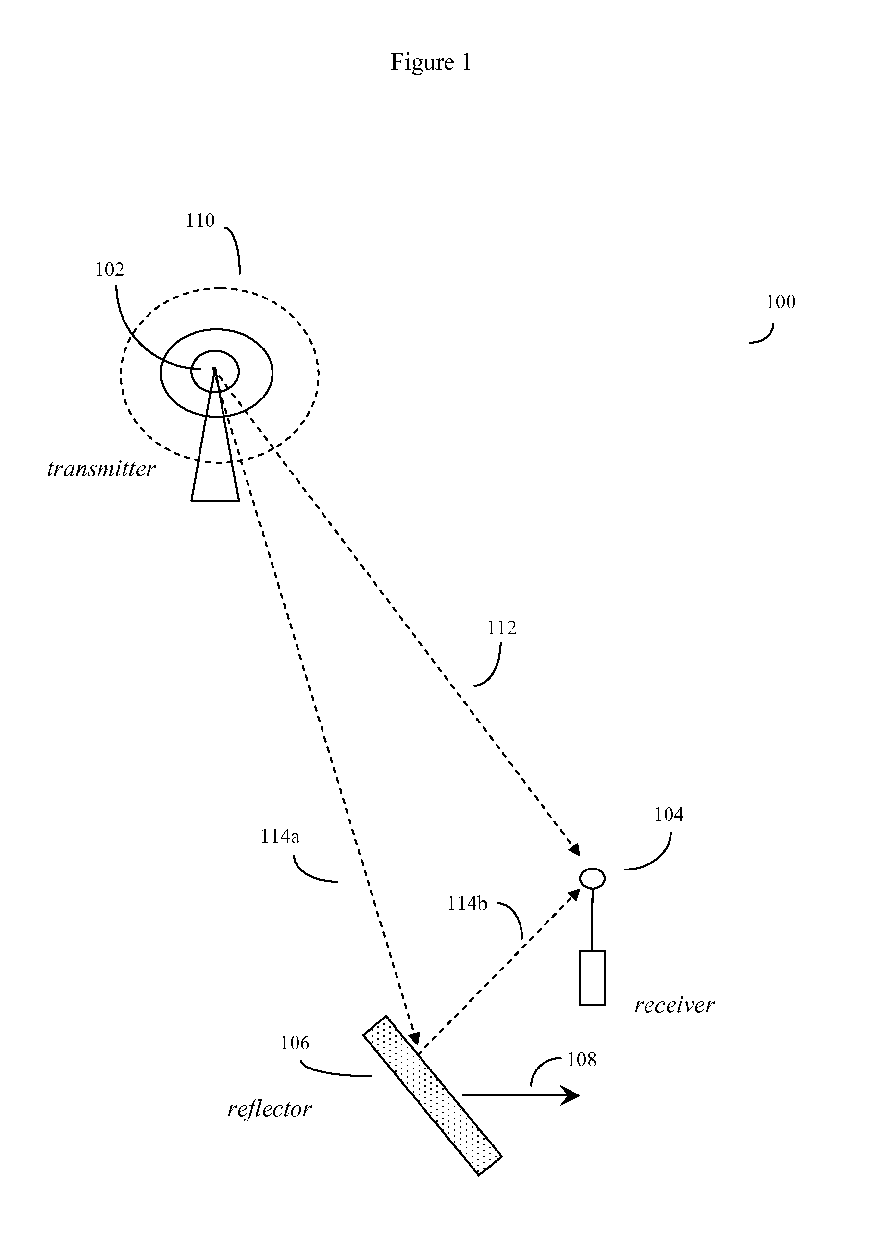
[0037]As previously discussed, the invention is based in part on the insight that in contrast to prior art methods that tended to view variations in signal strength (e.g. occasional signal fading, how long a signal remains coherent, how large a range of signal frequency ranges can be expected to be coherent) as something that can only be handled by statistical methods, superior results can be obtained if the underlying structure of a communications channel is exposed, and the various causes of signal distortion (e.g. various reflections, frequency shifts, other shifts and the like) are instead sorted out or “solved for”.

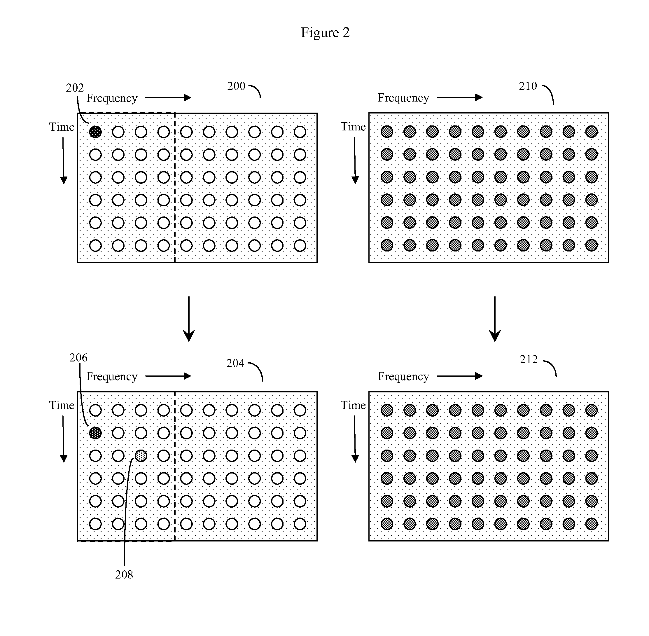
[0038]Since communication channels are used to transmit data, throughout this disclosure, generally communication channels will referred to as “data channels”. The main focus of this disclosure will be on wireless data channels that transmit data (often using radio signals of various frequencies up into the microwave frequencies and beyond) though three dimensions of...


PUM


Abstract

Computerized wireless transmitter / receiver system that automatically uses combinations of various methods, including transmitting data symbols by weighing or modulating a family of time shifted and frequency shifted waveforms bursts, pilot symbol methods, error detection methods, MIMO methods, and other methods, to automatically determine the structure of a data channel, and automatically compensate for signal distortions caused by various structural aspects of the data channel, as well as changes in channel structure. Often the data channel is a two or three dimensional space in which various wireless transmitters, receivers and signal reflectors are moving. The invention's modulation methods detect locations and speeds of various reflectors and other channel impairments. Error detection schemes, variation of modulation methods, and MIMO techniques further detect and compensate for impairments. The invention can automatically optimize its operational parameters, and produce a deterministic non-fading signal in environments in which other methods would likely degrade.

Description

CROSS REFERENCE TO RELATED APPLICATIONS[0001]This application claims the priority benefit of U.S. provisional application 62 / 027,213 “METHODS OF OPERATING AND IMPLEMENTING WIRELESS OTFS COMMUNICATIONS SYSTEMS”, filed Jul. 21, 2014; this application is also a continuation in part of U.S. patent application Ser. No. 15 / 853,911, “OTFS METHODS OF DATA CHANNEL CHARACTERIZATION AND USES THEREOF”, filed Dec. 29, 2014; this application is also a continuation in part of U.S. patent application Ser. No. 14 / 751,041 “ORTHONORMAL TIME-FREQUENCY SHIFTING AND SPECTRAL SHAPING COMMUNICATIONS METHOD”, filed Jun. 25, 2015; application Ser. No. 14 / 751,041 was a continuation of application Ser. No. 14 / 341,820, “ORTHONORMAL TIME-FREQUENCY SHIFTING AND SPECTRAL SHAPING COMMUNICATIONS METHOD”, filed Jul. 27, 2014, now U.S. Pat. No. 9,083,483 issued Jul. 14, 2015; application Ser. No. 14 / 341,820 was a continuation of application Ser. No. 13 / 117,119 filed May 26, 2011, now U.S. Pat. No. 8,879,378 issued Nov...

Claims


Application Information

Patent Timeline
Patent Type & Authority Applications(United States)
IPC IPC(8): H04B1/692H04L5/00
CPCH04L5/0007H04B1/692H04B7/10H04L5/0048H04L25/0212H04L25/0226H04L27/366H04B7/0626H04W24/02
Inventor RAKIB, SHLOMO SELIMHADANI, RONNY
Owner COHERE TECH
Why Eureka
Try Eureka