Eureka AIR delivers breakthrough ideas for toughest innovation challenges, trusted by R&D personnel around the world.

Ignition process and device for pairs of dbd electrodes

a technology of dbd electrodes and ignition processes, applied in the direction of chemical vapor deposition coatings, coatings, plasma techniques, etc., can solve the problems of reducing reducing the growth rate of the layer in the same manner. , to achieve the effect of improving the power factor of the installation, increasing the efficiency of the installation, and sufficient active energy

Inactive Publication Date: 2015-11-19
ASAHI GLASS CO LTD
View PDF6 Cites 0 Cited by
  • Summary
  • Abstract
  • Description
  • Claims
  • Application Information

AI Technical Summary

Benefits of technology

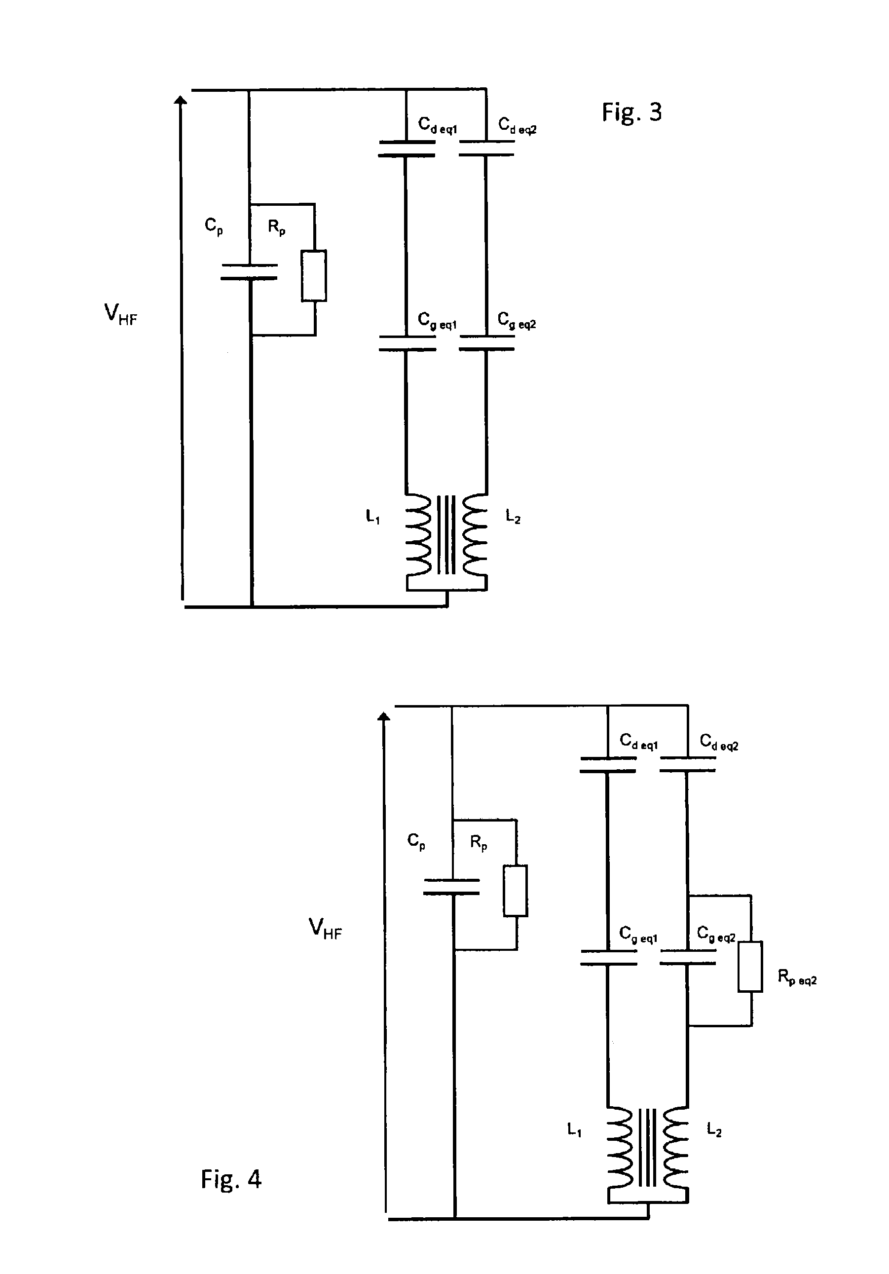
The invention is aimed at improving the efficiency and efficacy of a process. A preferred embodiment includes an adjustable inductance in the power supply circuit that modulates the phase shift between the voltage and the current. This allows for the generation of harmonics that extend the time the voltage is higher than required for the electric discharge. The adjustment of the power supply and the inductance can be done in a way that optimizes the production of harmonics.

Problems solved by technology

In such a process the virtually unavoidable consequence of small imperfections in the geometry of the electrodes and the counter-electrode or temperature differences is that the plasma preferably ignites under a single electrode.
This voltage no longer allows the ignition of the second electrode, since it is lower than the value of the sparkover voltage of the discharge.
The result is that the injected reactive product is lost to 50% and the growth rate of the layer is slowed down in the same manner.
This solution is not, of course, advantageous from the economic viewpoint since splitting of the transformer is costly.
However, during operation after ignition of the two electrodes this assembly entails boosting the supply of the reactor.

Method used


Image

  • Ignition process and device for pairs of dbd electrodes
  • Ignition process and device for pairs of dbd electrodes
  • Ignition process and device for pairs of dbd electrodes

Examples


Embodiment Construction

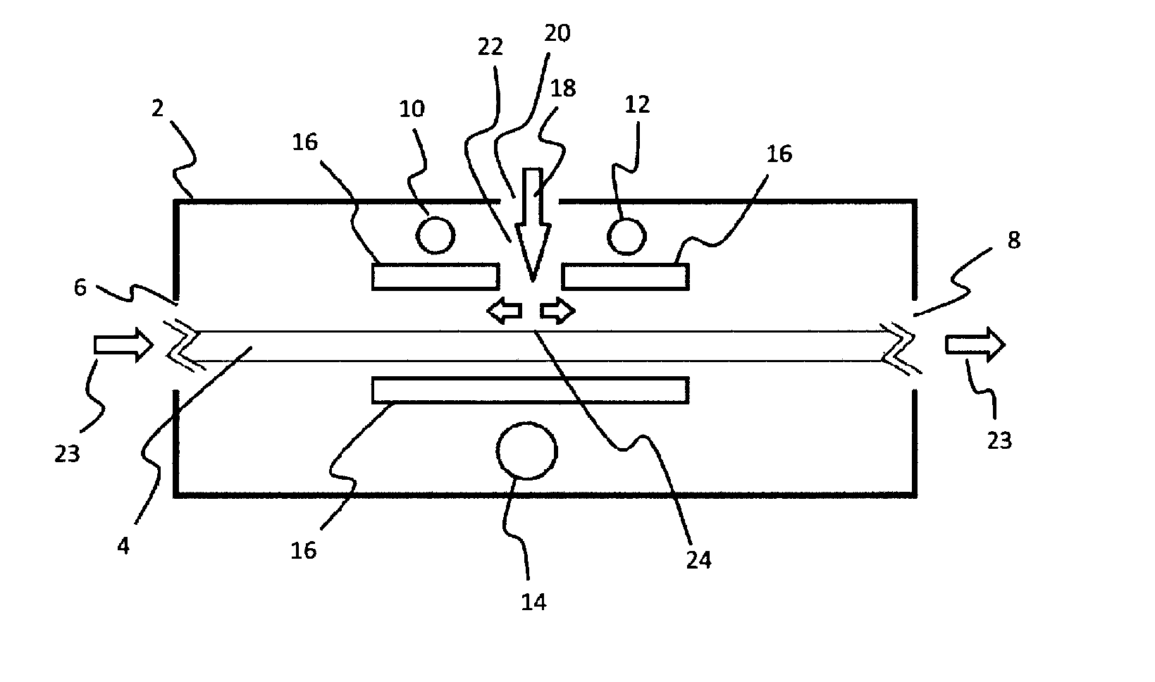
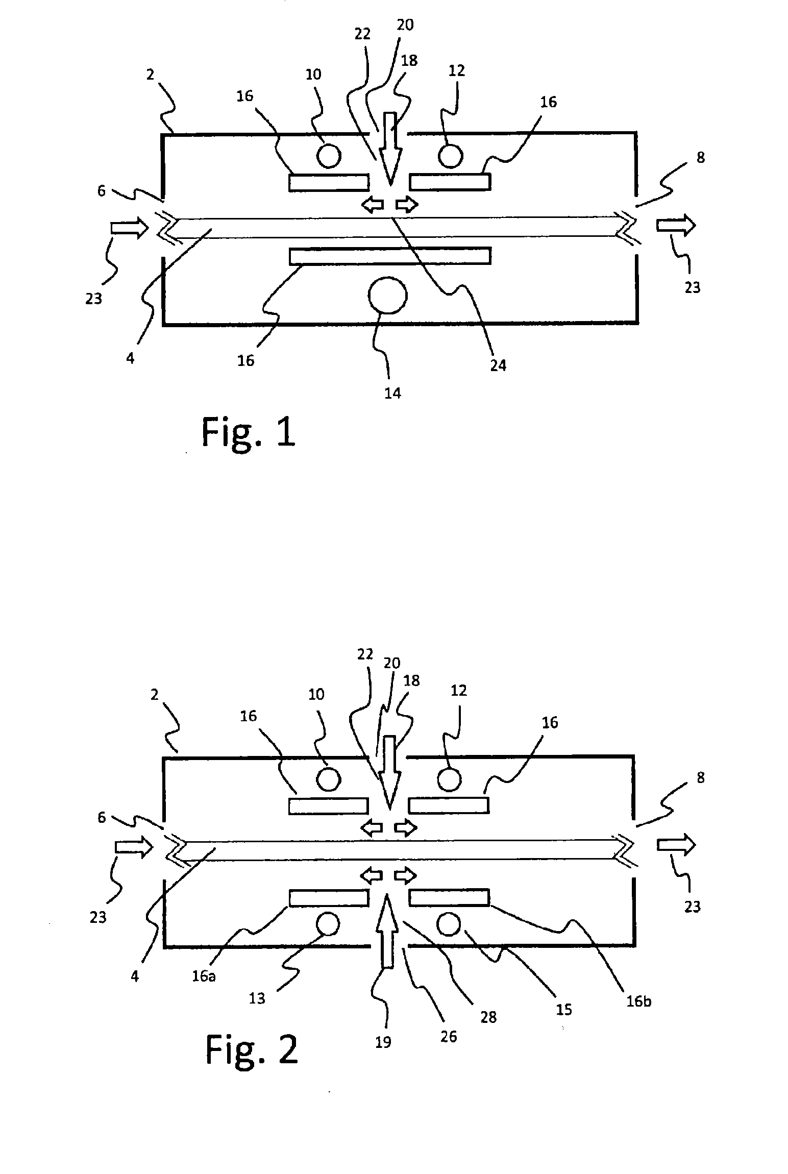
[0051]FIG. 1 shows an open chamber 2 designed for a continuous process for depositing layers on a glass substrate. The glass substrate 4 is inserted through an inlet 6, then passes inside this deposition chamber 2 before exiting again through an outlet 8. A high-frequency high voltage is applied between two electrodes 10, 12 and a counter-electrode 14. A dielectric barrier 16 is placed between the two electrodes 10, 12 and the counter-electrode 14. The difference in potential between the two electrodes 10, 12 and the counter-electrode 14 causes the generation of a plasma. A reactive mixture 18 is fed into the deposition chamber 2. Using multiple electrodes, below which the substrate 4 passes successively, results in the total surface area of the electrodes being increased. Compared to a process that only uses one electrode and one counter-electrode, this allows the thickness of the deposit to be increased or, alternatively with an identical thickness of deposit, allows the passage r...


PUM

PropertyMeasurementUnit
Dielectric polarization enthalpyaaaaaaaaaa
Pressureaaaaaaaaaa
Compositionaaaaaaaaaa

Abstract

A process for surface treatment by dielectric barrier discharge (DBD) comprising the following operations:—feeding or passing a substrate into a reaction chamber (2), in which at least two electrodes (10, 12) and at least one counter-electrode (13, 14, 15) are positioned, wherein at least one dielectric barrier (16) is placed between these at least two electrodes (10, 12) and this at least one counter-electrode (13, 14, 15);—switching an inductance (L1, L2) in series with each of said electrodes (10, 12), wherein said inductances (L1, L2) are wound onto a common magnetic core in such a manner that the resulting magnetic flux of the two inductances is zero when identical currents circulate in the two electrodes (10, 12);—generating a high-frequency electric voltage of such a value that it causes the generation of a plasma between the at least two electrodes (10, 12) and the at least one counter-electrode (13, 14, 15);—feeding into the reaction chamber a mixture, the composition of which is such that on contact with the plasma, it breaks down and generates substances able to react with the surface of the substrate (4);

Description

TECHNICAL FIELD[0001]The invention relates to dielectric barrier discharge processes for the surface treatment of substrates. In particular, the invention concerns the ignition when the surface treatment is conducted by at least two electrodes and at least one counter-electrode positioned on either side of the substrate.[0002]The invention also relates to an installation equipped with the ignition in question.BACKGROUND ART[0003]A process for depositing layers onto a substrate by dielectric barrier discharge is known from document EP 2145978. The described process includes in particular the insertion or passage of a substrate in a reaction chamber, in which an electrode and a counter-electrode are positioned. A dielectric barrier is placed between this electrode and this counter-electrode. A high-frequency electric voltage that causes the generation of a plasma is generated between the electrode and the counter-electrode. A gaseous composition is fed into the reaction chamber that u...

Claims


Application Information

Patent Timeline
IPC IPC(8): H01J37/32C23C16/455C23C16/50
CPCH01J37/32532C23C16/455C23C16/50H01J37/32174H01J37/32348
Inventor TIXHON, M. ERICMICHEL, M. ERICLECLERCQ, M. JOSEPH
Owner ASAHI GLASS CO LTD
Why Eureka
Eureka Blog
Learn More