
Thermal and/or pressure regulation control system

a control system and pressure regulation technology, applied in the field of control systems, can solve the problems of inability to provide optimal treatment of injuries without constant and close monitoring by medical practitioners, inaccurate systems, and relative crude temperature regulation, and achieve the effect of effective control and speeding up natural recovery

Inactive Publication Date: 2015-11-26
PHYSIOLAB TECH
View PDF0 Cites 58 Cited by
  • Summary
  • Abstract
  • Description
  • Claims
  • Application Information

AI Technical Summary

Benefits of technology

The present invention is a control system for regulating body temperature and pressure for the treatment of physical injuries and disorders. It helps speed up the natural recovery process.

Problems solved by technology

However, such ice packs and heat generating packs provide a relatively crude form of temperature regulation, unable to provide optimum treatment of an injury without constant and close monitoring by a medical practitioner.
While such control systems are known and have attempted to provide accurately controllable temperature regulation at the patient's skin, there are numerous variables which result in such systems being inaccurate.
Moreover, in such systems, particularly fluid based systems, it has been found difficult to produce the desired temperature at the actual site of the patient to be treated.
This is caused by a number of factors, of which the primary include difficulties in controlling the flow of fluid in an applicator cuff or garment, difficulties in ensuring proper energy transfer to the patient through the cuff, speed of energy transfer to the patient with consequential speed of adjustment of treatment parameters, and so on.
The prior art does not generally resolve the problems indicated above.

Method used


Image

  • Thermal and/or pressure regulation control system
  • Thermal and/or pressure regulation control system
  • Thermal and/or pressure regulation control system

Examples


Embodiment Construction

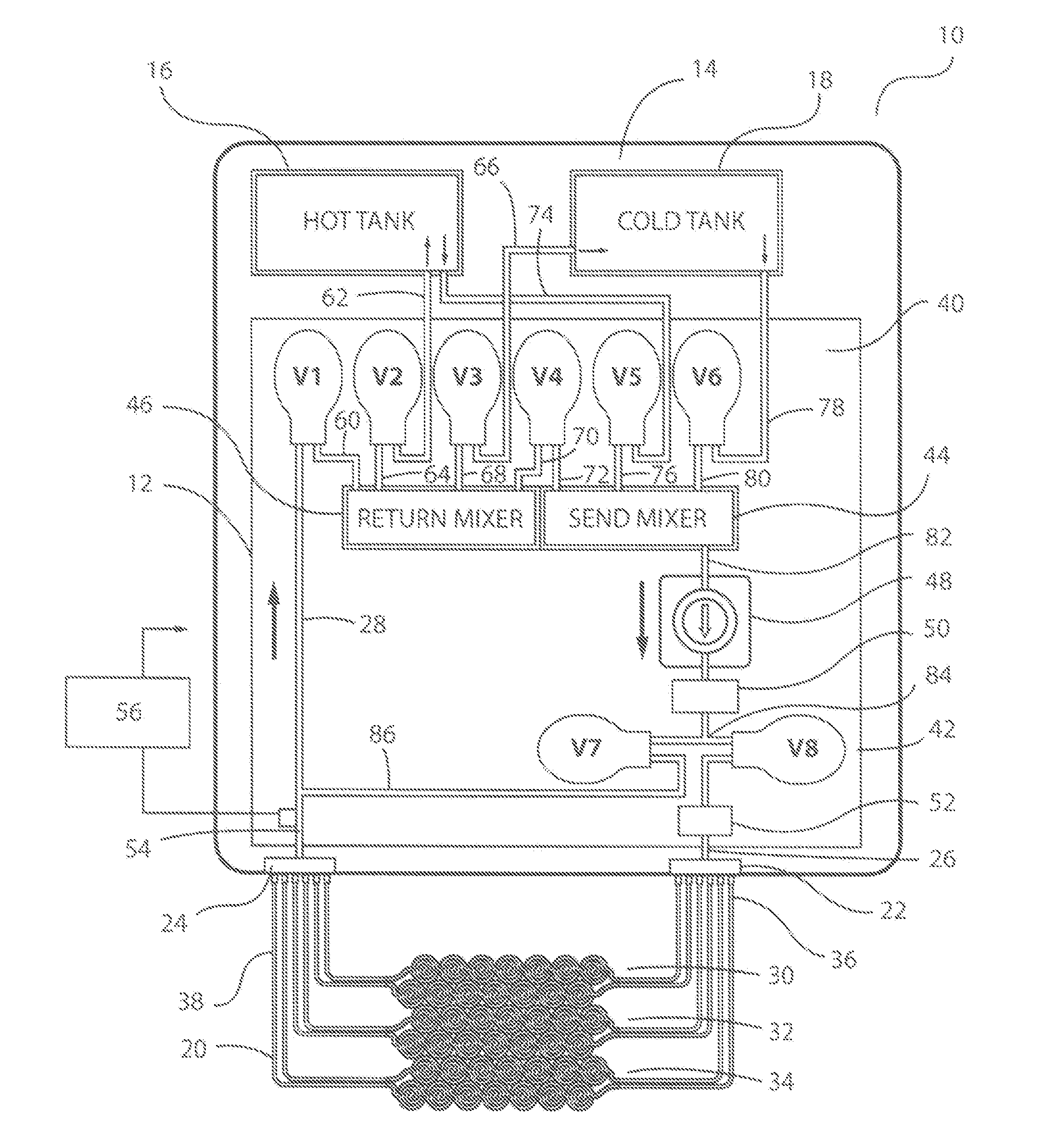
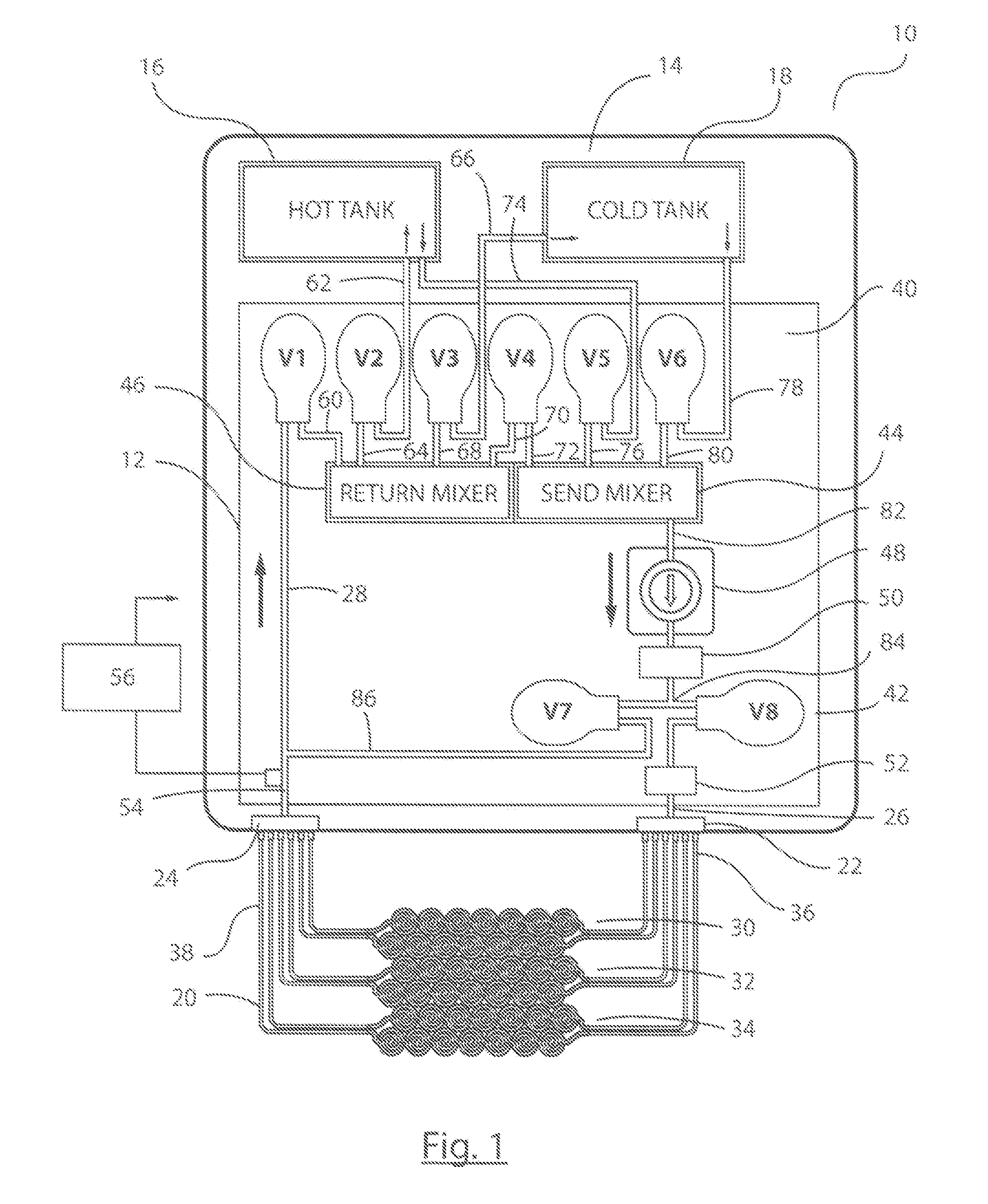
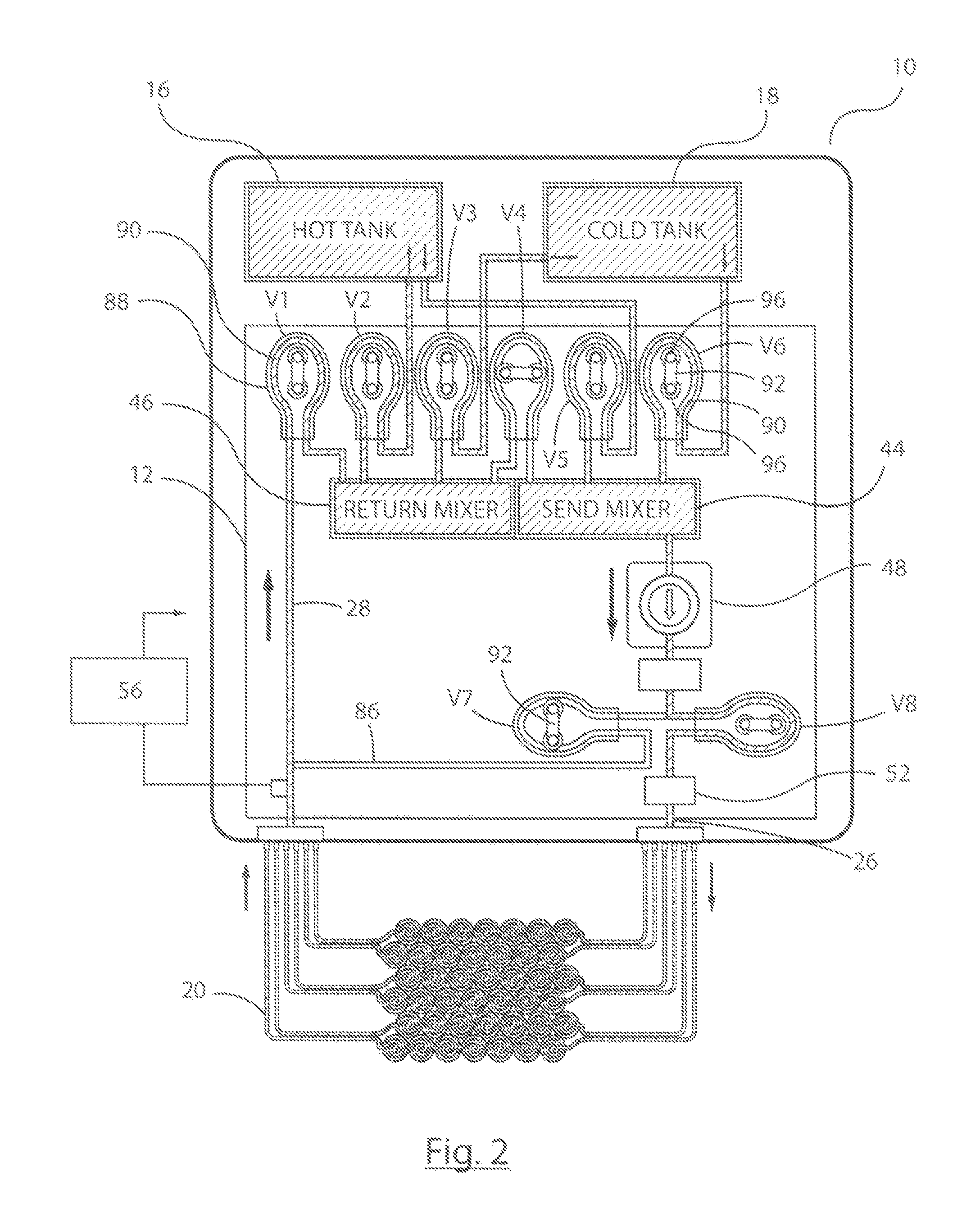
[0075]Described below are various embodiments of control system and method for a thermal and pressure regulation assembly used for providing thermal and / or pressure treatment to a patient. In some modes of operation, the system and method provide cryotherapy, that is the therapeutic application of a substance to the body that provides for the withdrawal of heat from the body so as to lower tissue temperature. The use of cryotherapy following musculoskeletal injury, trauma and pre and post-surgery is common practice and has been used for many years. This type of physical therapy has several advantages over other therapeutic measures because of its limited adverse effects, low cost and easy availability. The exact physiological responses to cryotherapy are still poorly understood but the range of the body's responses to cold can be summarised as:[0076]a) decreased metabolism;[0077]b) reduction in abnormal body temperature;[0078]c) effect on tissue inflammation (decreased or increased)...


PUM


Abstract

A control system for a thermoregulation assembly includes a fluid manifold assembly (12′) and a control unit (56′). The fluid manifold assembly includes a manifold output (26) for supplying thermoregulation fluid to an interface pack. The manifold assembly is operable to selectively provide thermoregulation fluid into the interface pack in accordance with feed parameters. The control unit (56′) can obtain a desired temperature profile and a conversion algorithm, the conversion algorithm providing a formula for deriving one of more feed parameters for bringing the interface pack to or maintaining the interface pack at a desired temperature dependent upon a characteristic energy transfer rate between a user and the interface pack. The control unit (56′) is operable to calculate one or more feed parameters from the desired temperature profile and the conversion algorithm and to operate the manifold assembly (12′) in accordance with the one or more feed parameters.

Description

TECHNICAL FIELD[0001]The present invention relates to a control system for a thermoregulation assembly used to apply thermal and / or compression treatment to a patient in order to alleviate or cure physical injuries and disorders.BACKGROUND ART[0002]There are numerous instances where it is desired to effect a thermal treatment on a patient alone or in combination with compression. For example, this may be to treat a physical injury, such as of the muscles, ligaments, tendons and the like. It may also be useful in treating skin injuries, as well as illnesses such as infections and so on as well as to accelerate natural recovery.[0003]Thermal treatments of this type have been known for many years, in their simplest form being ice packs. Heat generating packs have also been developed, typically in the form of a pouch of chemical material which can be made to react exothermically and thereby to release heat. These devices are intended to cool or heat, as appropriate, a part of a person's...

Claims


Application Information

Patent Timeline
Patent Type & Authority Applications(United States)
IPC IPC(8): A61F7/00
CPCA61F7/0085A61F2007/0095A61F2007/0056A61F2007/0029A61F2007/0039A61F2007/0091A61F2007/0296
Inventor ROSE, NICHOLASHASKINS, MARK
Owner PHYSIOLAB TECH
Learn More