
Membrane supports with reinforcement features

a technology of reinforcement features and membrane supports, applied in the direction of material analysis using wave/particle radiation, instruments, laboratories, etc., can solve the problems of limiting the sample size that could be imaged, and affecting the accuracy of measurement results

Inactive Publication Date: 2015-11-26
PROTOCHIPS
View PDF3 Cites 10 Cited by
  • Summary
  • Abstract
  • Description
  • Claims
  • Application Information

AI Technical Summary

Benefits of technology

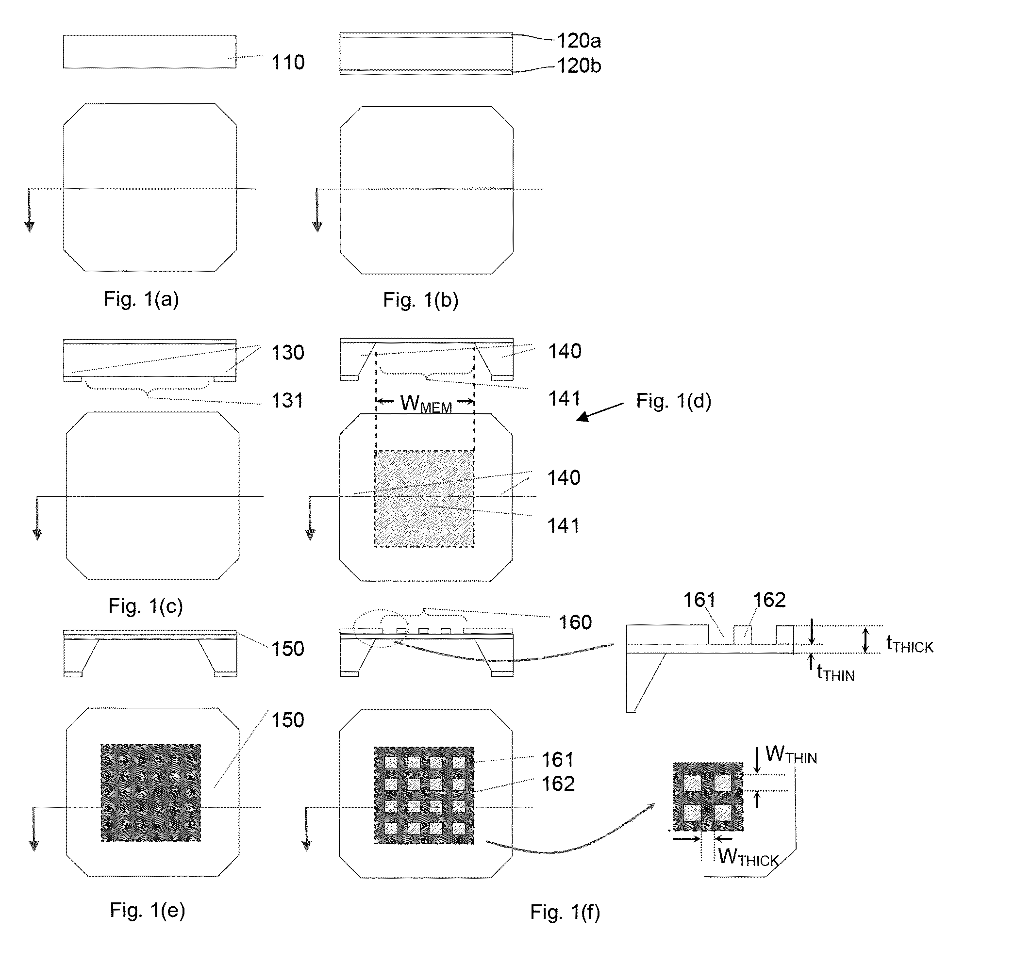
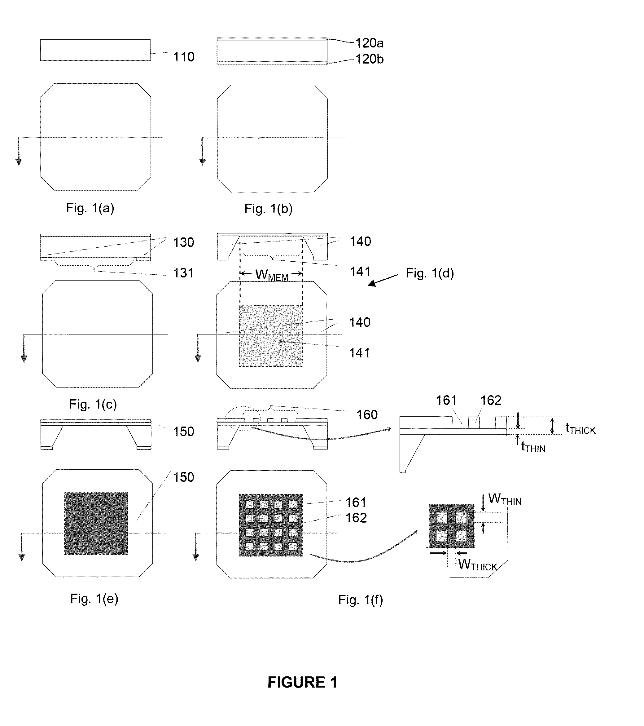
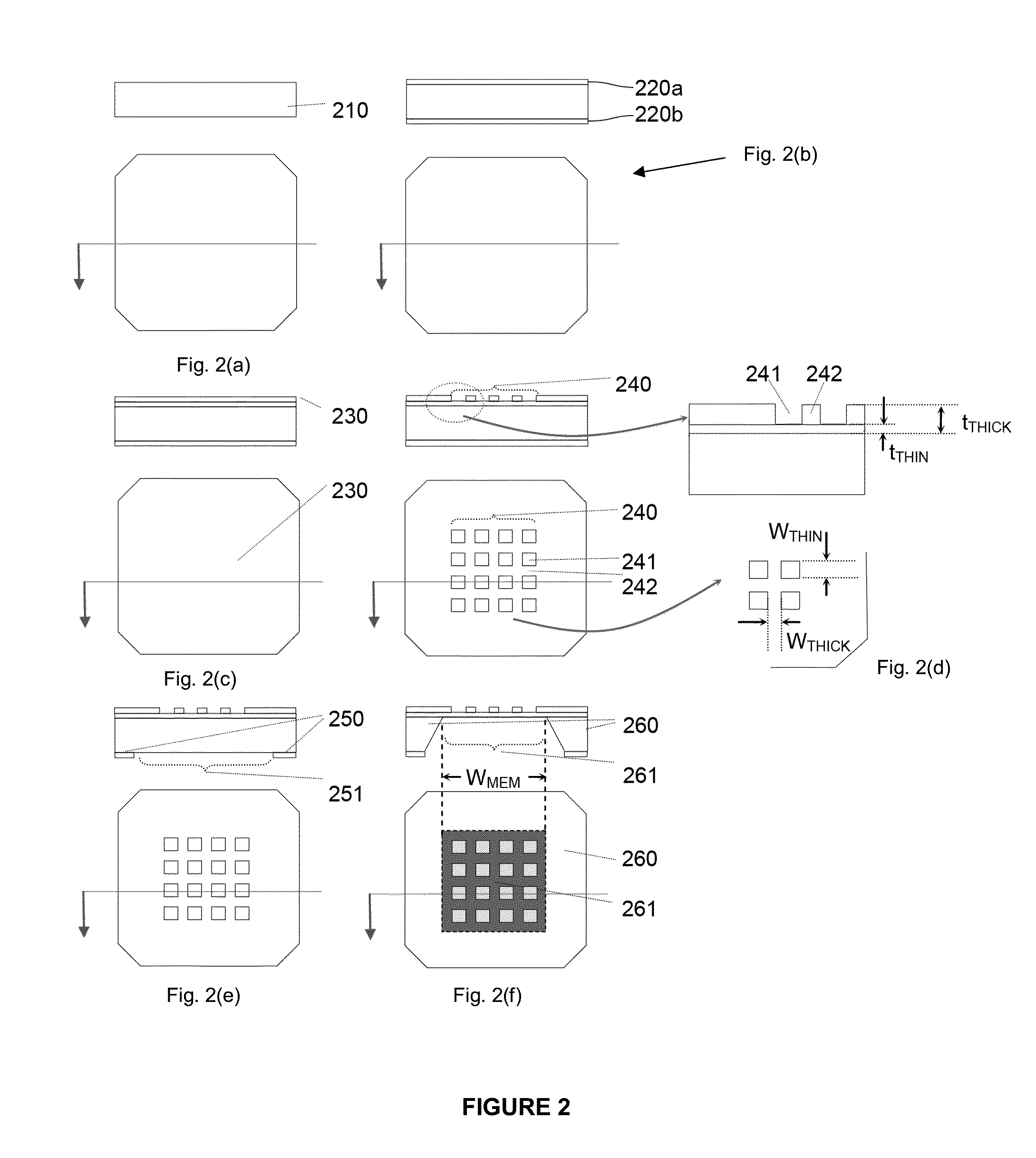
The invention is about a sample support structure that includes a reinforcement region to support viewing regions. The method of making the structure involves depositing layers of support and reinforcement on a substrate, and then removing portions of the layers to create the viewing regions. The resulting structure provides a stable and reliable support for viewing samples during analysis. Additionally, the invention includes a method for making a sample support structure with a membrane region and at least one spacer, which are made of the same material and are monolithic. This membrane region can be used for various applications such as membrane filtration or sample analysis.

Problems solved by technology

One concern that emerges for extremely thin membranes is strength; as the thickness of the membrane decreases, it is more likely to break during handling and burst if a differential pressure is applied across the membrane.
In theory, one could continue shrinking the membrane region to extremely small dimensions to achieve a high burst pressure for a given membrane thickness, but a tiny membrane region would be difficult to use in situ, would restrict the sample size that could be imaged, and is generally not useful for microscopy or spectroscopy techniques.

Method used


Image

  • Membrane supports with reinforcement features
  • Membrane supports with reinforcement features
  • Membrane supports with reinforcement features

Examples


Embodiment Construction

[0020]The present invention relates to sample support structures, methods of making sample support structures, and methods of using sample support structures. The sample support structures are useful for supporting samples for analysis using microscopic techniques, such as electron microscopy, optical microscopy, x-ray microscopy, UV-VIS spectroscopy and nuclear magnetic resonance (NMR) techniques.

[0021]As defined herein, “semiconductor” means a material, such as silicon, that is intermediate in electrical conductivity between conductors and insulators.

[0022]As defined herein, “photolithography” means a process, which uses beams of light, projected through a reticle, to pattern or etch a photosensitive material.

[0023]As defined herein, “frame” means a rigid region around the perimeter of a sample support structure that is used to provide mechanical support to the entire structure (preferred embodiments include a silicon frame selectively etched using KOH, a silicon frame selectively...


PUM


Abstract

A sample support structure with integrated support features and methods of making and using the reinforced membrane. The sample support structures are useful for supporting samples for analysis using microscopic techniques, such as electron microscopy, optical microscopy, x-ray microscopy, UV-VIS spectroscopy and nuclear magnetic resonance (NMR) techniques.

Description

CROSS REFERENCE TO RELATED APPLICATIONS[0001]This application is a Continuation-in-Part (CIP) and claims priority to U.S. patent application Ser. No. 12 / 529,429 filed on Feb. 16, 2010 entitled “Membrane Supports with Reinforcement Features” in the name of John Damiano Jr., et al., now U.S. Pat. No. 9,040,939 issued on May 26, 2015, which is a 35 U.S.C. §371 filing claiming priority to International Patent Application No. PCT / US2008 / 055435 filed on Feb. 29, 2008, which claims priority of U.S. Provisional Patent Application No. 60 / 892,677 filed on Mar. 2, 2007, all of which are hereby incorporated by reference herein in their entirety.FIELD OF THE INVENTION[0002]The invention relates to a reinforced membrane with integrated support features and to a membrane with spacers and methods of making and using the membrane.BACKGROUND OF THE INVENTION[0003]Very thin membranes are useful as sample supports for electron microscopy. Extremely thin membranes (<50 nm) are nearly electron transpa...

Claims


Application Information

Patent Timeline
IPC IPC(8): G01N1/36
CPCG01N1/36G01N23/20025G02B21/34H01J37/26H01J2237/2003H01J37/20H01J37/00H01J37/3178
Inventor DAMIANO, JR., JOHNMICK, STEPHEN E.NACKASHI, DAVID P.DUKES, MADELINE
Owner PROTOCHIPS
Learn More