An automatic checking method for clock synchronization and specialized apparatus thereof

Active Publication Date: 2015-11-26
STATE GRID CORP OF CHINA +1
3 Cites 9 Cited by

AI-Extracted Technical Summary

Problems solved by technology

However, in actual use, once the Beidou signal source fails, the synchronization signal comparison module is not automatically switched to the GPS signal source, and meanwhile the alarming ...

Benefits of technology

[0004]The present invention is aimed to overcome the shortages of the prior art and provide an autom...

Abstract

The invention relates to an automatic checking method for clock synchronization, comprising the following steps: (1) regularly acquiring clock signals sent by a Beidou signal source, a GPS signal source and an SNTP signal source; (2) performing subtraction to the clock signals of the Beidou signal source and the GPS signal source and evaluating the absolute value of the difference; at the same time, performing subtraction to the clock signals of the Beidou signal source and the SNTP signal source and then evaluating the absolute value of the difference and finally judging the results of the two differences; and (3) constantly repeating steps (1) and (2). The operations in the present invention can efficiently avoid the problems in the existing technology, guarantee the consistency and accuracy of system time, and guarantee the stable and safe operation of the system and the normal operation of other power grid businesses.

Application Domain

Time-division multiplexTransmission

Technology Topic

VIT signalsPower grid +7

Image

  • An automatic checking method for clock synchronization and specialized apparatus thereof
  • An automatic checking method for clock synchronization and specialized apparatus thereof
  • An automatic checking method for clock synchronization and specialized apparatus thereof

Examples

  • Experimental program(1)

Example

[0027]The present invention is further illustrated below in conjunction with embodiments. The embodiments below are illustrative and not for limiting the scope of protection of the present invention.
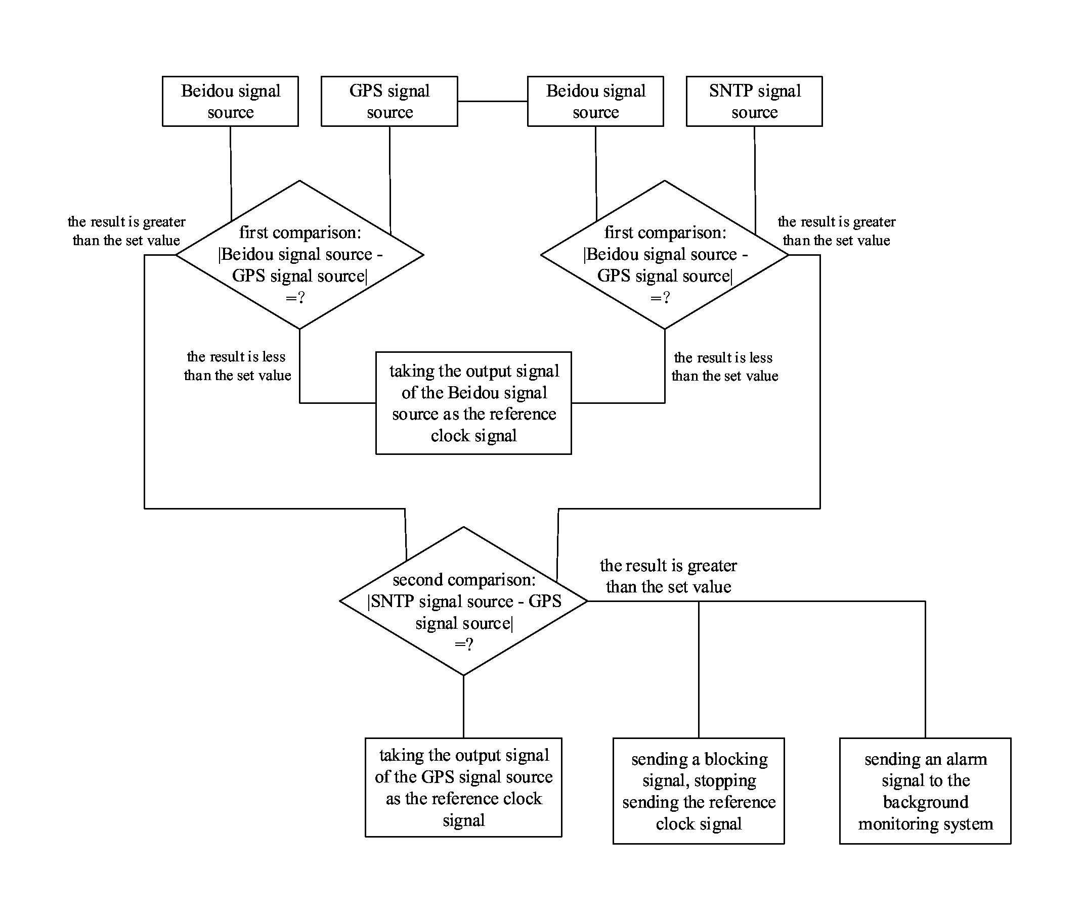
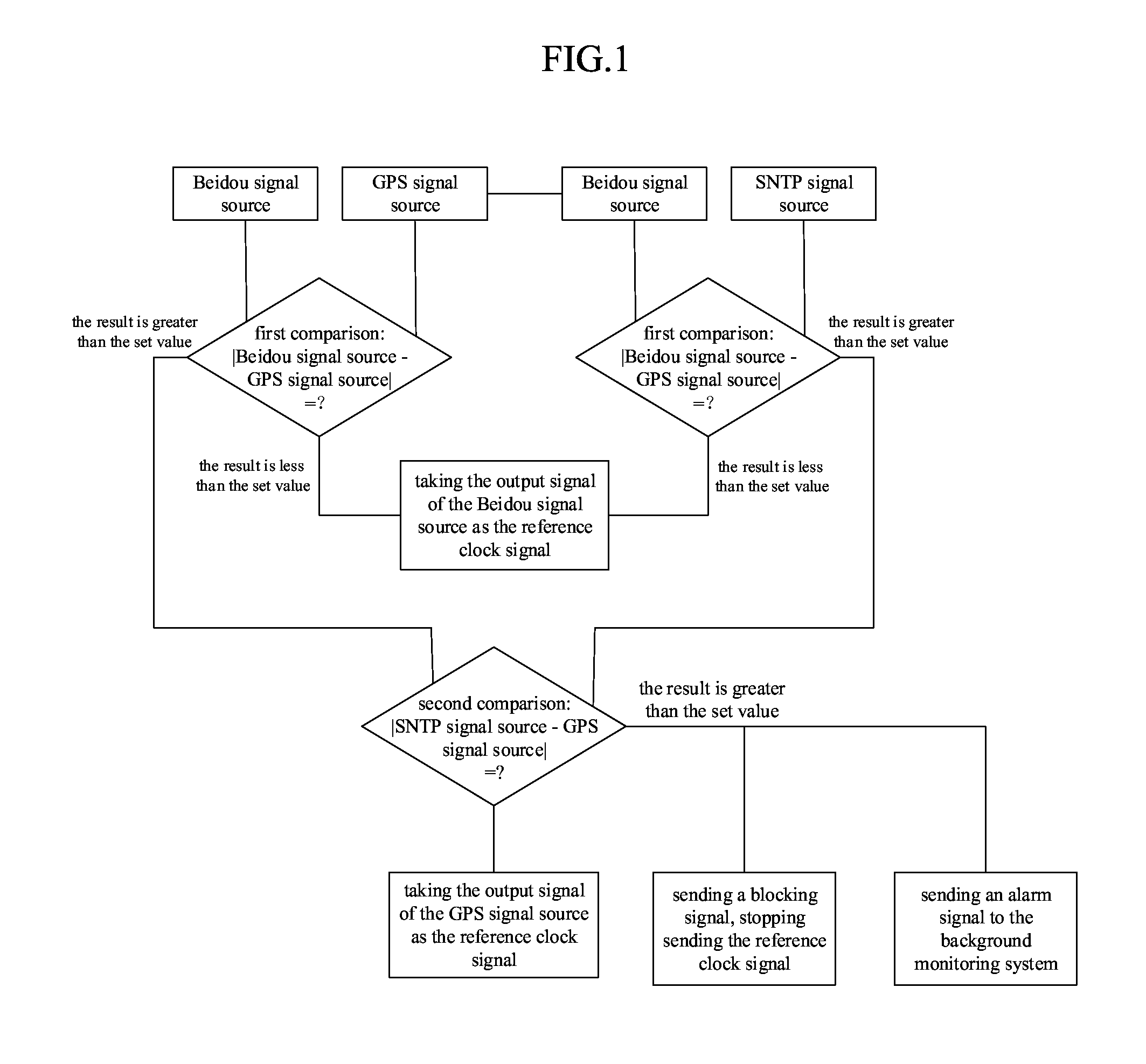
[0028]As shown in FIG. 1, the innovation of an automatic checking method for clock synchronization of the present invention is that it comprises the following steps: [0029] (1) Regularly acquiring clock signals sent by a Beidou signal source, a GPS signal source and an SNTP signal source; [0030] (2) Performing subtraction to the clock signals of the Beidou signal source and the GPS signal source and evaluating the absolute value of the difference; at the same time, performing subtraction to the clock signals of the Beidou signal source and the SNTP signal source and then evaluating the absolute value of the difference; and finally judging the results of the two differences: [0031] a) When the two differences are less than the preset value, outputting the clock signal of the Beidou signal source to each synchronization signal receiving apparatus as a reference clock signal; and [0032] b) When any one of the differences is greater than the preset value, entering a secondary operation process; and [0033] (3) Constantly repeating steps (1) and (2);
[0034]The secondary operation comprises the following steps: [0035] (1) Performing subtraction to the clock signals of the GPS signal source and the SNTP signal source, and then evaluating the absolute value of the difference; [0036] (2) Judging the result of this difference: [0037] a) When the difference is less than the preset value, outputting the clock signal of the GPS signal source to each synchronization signal receiving apparatus as a reference clock signal; and [0038] b) When the difference is greater than the preset value, entering an alarm process;
[0039]The alarm process comprises the following steps: [0040] (1) Sending a blocking signal to a Beidou signal output module and a GPS signal output module and stopping the sending of the reference clock signal; and [0041] (2) Sending an alarm signal to a background monitoring system.
[0042]The cycle for regularly acquiring is 50 ms, and the preset value is 20 ms.
[0043]The abovementioned processes preferably employ the Beidou signal source. If the Beidou signal source fails, the GPS signal source is preferably employed, and if both the Beidou and the GPS signal sources fail, an alarm is output and the output of each clock signal is blocked.
[0044]The structure of the specialized apparatus used in the present invention is as shown in FIG. 2: comprising a Beidou signal receiving module, a GPS signal receiving module, a network module, a synchronization signal comparison module, a Beidou signal output module, a GPS signal output module and an alarming and blocking module, wherein the Beidou signal receiving module, the GPS signal receiving module, the clock synchronization comparison module, the Beidou signal output module, the GPS signal output module and the alarming and blocking module are components of the existing technology mainly for the automatic comparison of the Beidou signal and the GPS signal. However, in order to adapt to the automatic checking method of the present invention, a network module is further installed in a housing 1. The specific connection of various modules is that the Beidou signal receiving module, the GPS signal receiving module, the network module, the synchronization signal comparison module, the Beidou signal output module, the GPS signal output module and the alarming and blocking module are installed in the housing; a port of the synchronization signal comparison module is connected with the respective ends of the Beidou signal receiving module, the GPS signal receiving module, the network module, the Beidou signal output module, the GPS signal output module and the alarming and blocking module, respectively; the other ends of the Beidou signal receiving module, the GPS signal receiving module and the network module are connected with a Beidou signal source, a GPS signal source and an SNTP signal source, respectively; the other ends of the Beidou signal output module and the GPS signal output module are both connected with a respective reference clock signal input end of a plurality of synchronization signal receiving apparatuses; the other end of the alarming and blocking module is connected with an alarm signal input end of the background monitoring system; and two blocking signal output ends of the alarming and blocking module are connected with a respective blocking signal input end of the Beidou signal output module and the GPS signal output module.
[0045]The abovementioned network module can adopt a wireless transmission mode (i.e., a hardware module supporting wireless transmission), and also can adopt a wired transmission mode (i.e., a hardware module connected by a network cable). Both kinds of modules can acquire the clock signal output by the SNTP signal source. The abovementioned alarm signal is of a high level for triggering the background monitoring system, and the blocking signal is of a high level for blocking the Beidou signal output module and the GPS signal output module.
[0046]In the present invention, the three clock signals output by the Beidou signal source, the GPS signal source and the SNTP signal source are taken as the original clock signals. Subtraction is then performed to the Beidou signal and the GPS signal, and at the same time to the Beidou signal and the SNTP signal. The absolute values of the two differences are evaluated and are then compared with the preset value. If the differences exceed the preset value, subtraction is performed to the GPS signal and the SNTP signal. Finally, the results can determine the signal source by which the clock signal output is taken as the reference clock signal of a plurality of synchronization signal receiving apparatuses. The abovementioned operations can efficiently avoid the problems in the existing technology, guarantee the consistency and accuracy of system time, and guarantee the stable and safe operation of the system and the normal operation of other power grid businesses.

PUM

no PUM

Description & Claims & Application Information

We can also present the details of the Description, Claims and Application information to help users get a comprehensive understanding of the technical details of the patent, such as background art, summary of invention, brief description of drawings, description of embodiments, and other original content. On the other hand, users can also determine the specific scope of protection of the technology through the list of claims; as well as understand the changes in the life cycle of the technology with the presentation of the patent timeline. Login to view more.

Similar technology patents

Multifunctional transport packaging frame for hollow glass

InactiveCN106429444ASimple designScientific and reasonable
Owner:洛阳新东昊玻璃有限公司

Laser radar optical system with optical axis calibrating function and optical axis calibrating method

InactiveCN102353950AOptical axis alignment with high precisioneasy to operate
Owner:INST OF APPLIED ELECTRONICS CHINA ACAD OF ENG PHYSICS +1

Tension control device for bent pipe anti-corrosion composite belt

PendingCN108439065ASimple structural designScientific and reasonable
Owner:LUOYANG INST OF SCI & TECH

Defrosting control method and device

ActiveCN104807132Aeasy to operateDefrost is reasonable
Owner:GREE ELECTRIC APPLIANCES INC OF ZHUHAI

Micro fit clearance screw of plastic film extruder

PendingCN113352572ASimple designScientific and reasonable
Owner:洛阳市大资塑业有限公司

Classification and recommendation of technical efficacy words

  • scientific and reasonable
  • easy to operate

Multifunctional transport packaging frame for hollow glass

InactiveCN106429444ASimple designScientific and reasonable
Owner:洛阳新东昊玻璃有限公司

Micro fit clearance screw of plastic film extruder

PendingCN113352572ASimple designScientific and reasonable
Owner:洛阳市大资塑业有限公司

Tension control device for bent pipe anti-corrosion composite belt

PendingCN108439065ASimple structural designScientific and reasonable
Owner:LUOYANG INST OF SCI & TECH

Lancet device

InactiveUS7303573B2inexpensively mass-producedeasy to operate
Owner:ABBOTT DIABETES CARE INC

Rapid and non-invasive optical detection of internal bleeding

InactiveUS20050065436A1easy to operaterapid and accurate result
Owner:HO WINSTON ZONH +2
Why Eureka
Try Eureka