Multi-functional composite structures

a composite structure and multi-functional technology, applied in the field of wire harnesses, can solve the problems of affecting the service life of the wire harness, so as to improve the current distribution, facilitate the soldering, and improve the effect of implementation

Active Publication Date: 2015-12-03
AURORA FLIGHT SCI CORP
View PDF21 Cites 30 Cited by
  • Summary
  • Abstract
  • Description
  • Claims
  • Application Information

AI Technical Summary

Benefits of technology

[0118]As discussed above, ingress-egress may be accomplished using a PCB electrical connector electrically bonded to pad sites for signal cabling (e.g., 4 signal wires and 2 power wires). An alternative electrical connector may be a wire inserted directly into the layup. A benefit of this electrical connector is that it is simple to implement while also providing sufficient current distribution at the ingress-egress points such that not “hot spots” were created. Initial tests investigated using various wire gauge sizes to carry the same current ranging from a single 22 AWG wire to four 28 AWG wires. Wires were soldered to 40 gsm carbon veil with NiCVD pads. Multiple wires allowed better current distribution over the pad site and although were of greater number then a single 22 AWG wire, they were easier to solder and required less solder overall. However, because larger single wires may be required, a compromise was found by stripping the 22 AWG wire and unwinding and splaying (i.e., fanning) the individual copper strands. This was tested in two methods, one in which the copper strands were then bundled into 3 smaller pairs and on

Problems solved by technology

Wiring is costly to install, heavy, and vulnerable to damage from service (i.e., incorrectly routed near hot equipment and/or bundled together with other incompatible wire types such as soft wire laying adjacent to hard wire, etc.) and maintenance.
Moreover, all wire deteriorates in service due to environmental factors such as: extreme heat and cold temperature swings, humidity, salt damage associated with marine environments, contamination by aircraft fluids (i.e., fuel, oil, hydraulic fluid, de-icing fluid, cleaning chemicals, toilet residue, galley spillage, etc.), as well as in-flight vibration causing chafing of wires rubbing against other wires or the structure of the aircraft.
These conditions make it extremely difficult to protect any circuit in such a bundle, where an insulation failure could result in an electrical problem that has multiple

Method used


Image

  • Multi-functional composite structures
  • Multi-functional composite structures
  • Multi-functional composite structures

Examples


Embodiment Construction

[0039]Preferred embodiments of the present invention will be described hereinbelow with reference to the accompanying drawings. In the following description, certain well-known functions or constructions are not described in detail since they would obscure the invention in unnecessary detail. For this application the following terms and definitions shall apply:

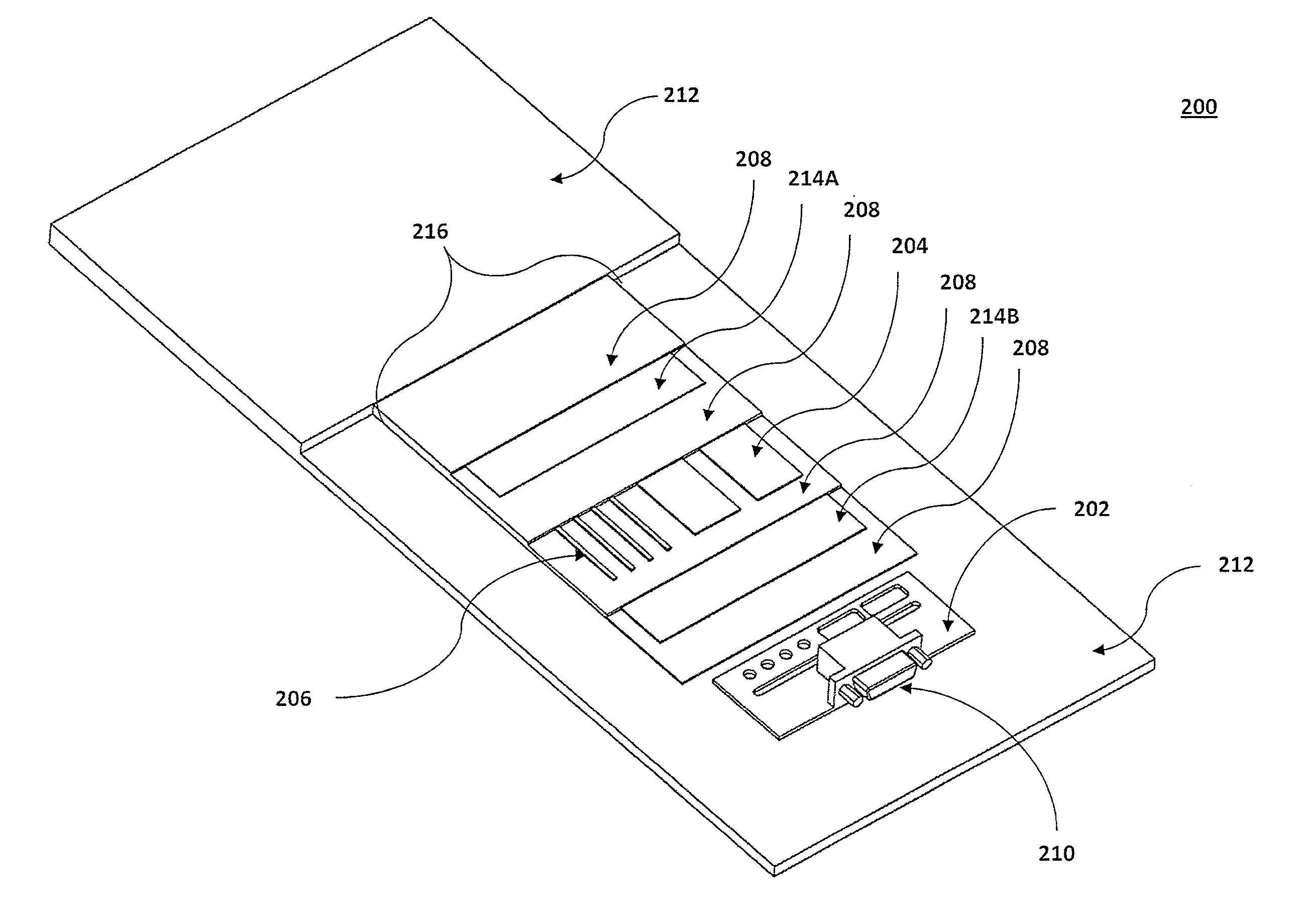
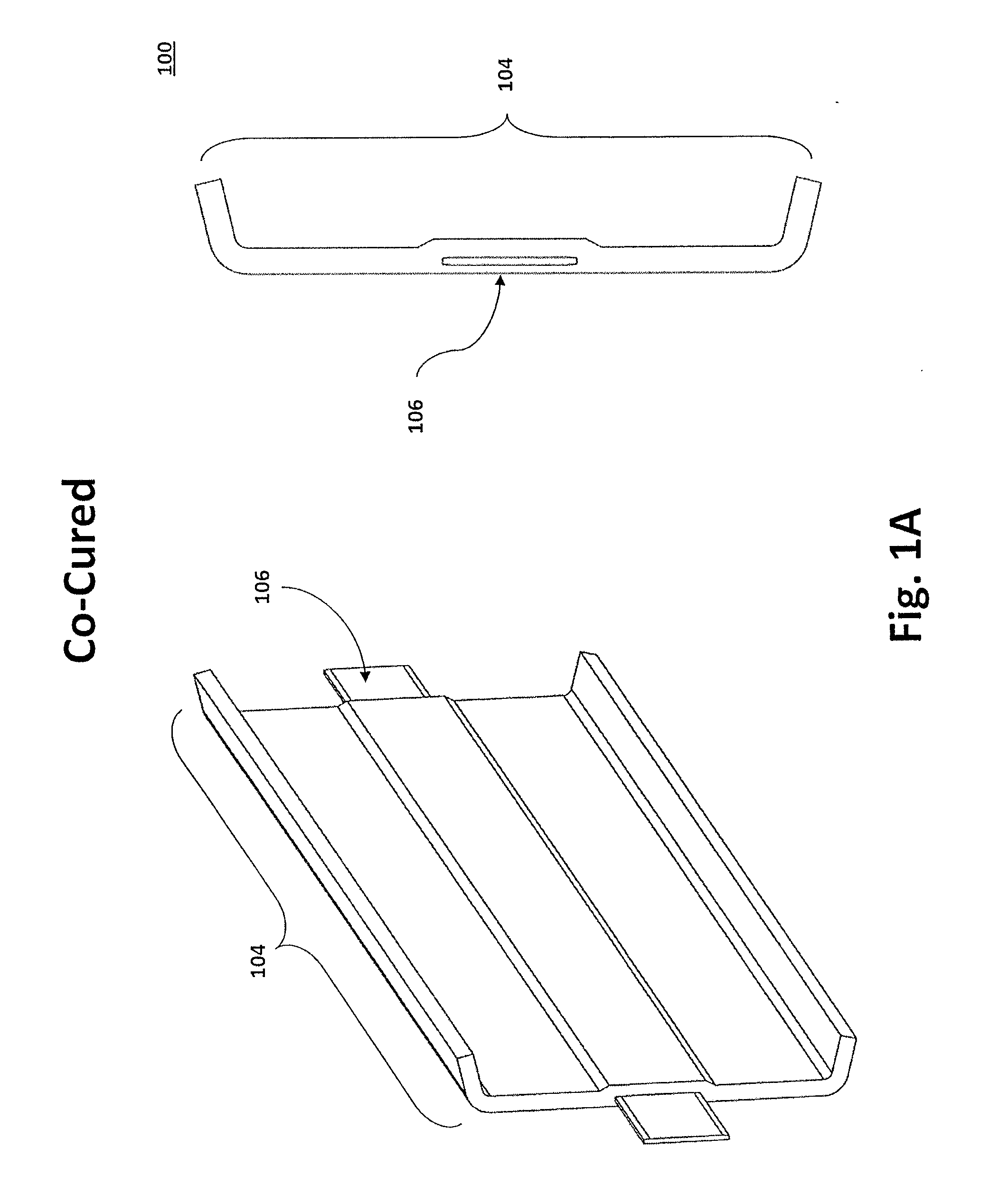
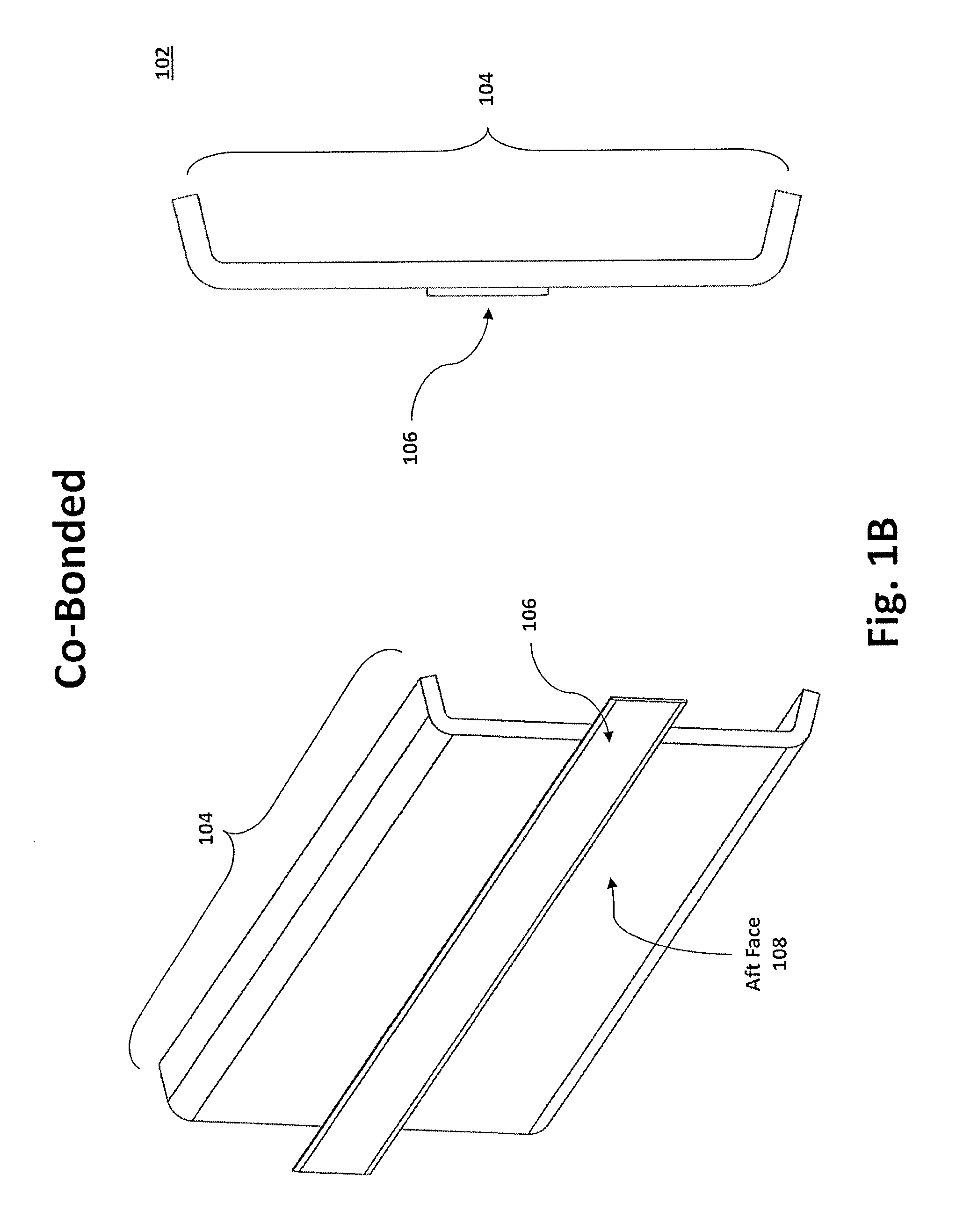
[0040]The term “conductor sandwich assembly” (“CSA”) as used herein describes the structure formed when one or more conductors (e.g., carbon, metal, NiCVD, etc.) are sandwiched between insulating layers of material such that the conductor is electrically isolated and structural loads (i.e., shear, tension, compression, bending, and combined loads) can be passed therethrough. As discussed herein, a CSA may be configured to carry power and / or signals via the one or more conductor traces. A CSA may further include one or more shielding layers to reduce, or eliminate, interference to any signal carrying conductors or by any power ...


PUM

PropertyMeasurementUnit
Poweraaaaaaaaaa
Electrical resistanceaaaaaaaaaa
Currentaaaaaaaaaa

Abstract

A multi-functional composite system, the multi-functional composite system comprising a core, a plurality of structural composite fiber layers, a matrix material, a composite conductor assembly, the composite conductor assembly having one or more conductors disposed between two or more insulating layers, and an electric power source electronically coupled with said composite conductor assembly, the electric power source is configured to pass electric current through at least one of said one or more conductors.

Description

[0001]This application is a Non-provisional of U.S. Patent Application No. 62 / 007,375, filed Jun. 3, 2014, the contents of both incorporated herein by reference.STATEMENT OF GOVERNMENT INTEREST[0002]This invention was made with government support under Contract Number: FA8650-11-C-3110 awarded by United States Air Force. The government has certain rights in the invention.TECHNICAL FIELD[0003]The present invention relates generally to wiring and wire harnesses. More particularly, the invention relates to apparatus and method for an aircraft conductor sandwich assembly embedded to an aircraft structural member.BACKGROUND INFORMATION[0004]Modern air vehicles contain many miles of electrical power and signal wiring. Wiring is costly to install, heavy, and vulnerable to damage from service (i.e., incorrectly routed near hot equipment and / or bundled together with other incompatible wire types such as soft wire laying adjacent to hard wire, etc.) and maintenance. Moreover, all wire deterio...

Claims


Application Information

Patent Timeline
IPC IPC(8): B64D15/12H05B3/28
CPCB64D15/12Y10T29/49085H05B3/286B64C1/12B64D45/00H05B2214/02H05B2214/04Y02T50/50
Inventor WEN, EDCOTTRELL, DANEHRMANTRAUT, ADAMBLEHAR, MARKKORDONOWY, DAVID
Owner AURORA FLIGHT SCI CORP
Why Eureka
Try Eureka