Stable grounding system to avoid catastrophic electrical failures in fiber-reinforced composite aircraft

a fiber-reinforced composite aircraft and stable grounding technology, which is applied in the direction of structural/machine measurement, instruments, transportation and packaging, etc., can solve the problems of catastrophic delaminate, significant loss of life and aircraft damage, and catastrophic failure of fiber-reinforced composite materials

Inactive Publication Date: 2015-12-03
SMART DRILLING & COMPLETION
View PDF4 Cites 33 Cited by
  • Summary
  • Abstract
  • Description
  • Claims
  • Application Information

AI Technical Summary

Benefits of technology

[0102]In addition, the sensor array provided by an intelligent patch may have a variety of other uses and may be made of different materials, including steel, aluminum or alloys of the same. The patch may be a metal mesh combined with fiberglass or composite fiber material. The patch may be used to temporarily or permanently fix aluminum bodies in aircraft, automobiles, steel portions in ship hulls, and metal tanks and pipelines. For example, a ship with a breached hull may utilize a metal intelligent patch in a situation requiring a quick temporary fix. The sensor array can provide feedback to the ship's crew regarding its viability and leakage on an on-going basis.
[0103]Another object of the invention is to provide methods and apparatus to detect, measure, and determine the presence of unknown Groundloop currents flowing through unidentified circuit pathways within the wiring system distributed within a portion of a fuselage of an airplane substantially made from fiber-reinforced composite materials to avoid catastrophic failures of the electrical system within such an airplane.

Problems solved by technology

Catastrophic failures of fiber-reinforced composite materials have proven to be a problem in the oil and gas industries.
Any catastrophic failure of fiber-reinforced wings and / or wing junction boxes or other structural components during flight would likely result in significant loss of life and the destruction of the aircraft.
A problem with composites is that they catastrophically delaminate under certain circumstances.
Williams' assessments, clearly compressive forces applied to composites can cause significant problems.
Consequently, in such areas subject to compressive stresses, microfractures will allow, for example, water, water vapor, fuel, grease, fuel vapor, and vapors from burned jet fuel to enter these microfractures, that in turn, could cause a catastrophic failure of the wing and / or the wing junction box—possibly during flight.
Similar catastrophic problems could arise at other locations including composite materials.
So, it may not be wise to extrapolate the “no problems in the military argument” to the exposure of wings and wing boxes in civil commercial aircraft, including those of the 787, to at least some substantial repetitive compressive forces that may also be simultaneously subject to long-term environmental contamination by ambient fluids and gases.
But engineers don't completely understand how aircraft made of composite materials will respond to the stresses of actual flight.
If engineers continue to be surprised by the 787's response to real-world operating stresses, there is some possibility that the testing process might not catch all the potential problems with the design and construction of the aircraft.”
Significant problems have occurred in the past during the development of new airframes.
For example, inadequate attention was paid the possibility of high stresses causing catastrophic metal fatigue during the development of the de Havilland Comet.
High stresses were a surprise particularly around the square window corners.
Such failure of adequate attention resulted in several notable crashes.
Water entering into an epoxy-aluminum bonded area caused the basic problem.
Consequently, an epoxy resin failure between two laminated materials (in this case aluminum) has caused significant problems in the past.
Damage to the fuselage can occur in numerous ways, including from pilots dragging the tail of the plane on the runway, and from service vehicles colliding with the nose, and the fuselage near passenger and cargo doors.

Method used


Image

  • Stable grounding system to avoid catastrophic electrical failures in fiber-reinforced composite aircraft
  • Stable grounding system to avoid catastrophic electrical failures in fiber-reinforced composite aircraft
  • Stable grounding system to avoid catastrophic electrical failures in fiber-reinforced composite aircraft

Examples


Embodiment Construction

[0119]The following description will typically be with reference to specific structural embodiments and methods. It is to be understood that there is no intention to limit the invention to the specifically disclosed embodiments and methods but that the invention may be practiced using other features, elements, methods and embodiments. Preferred embodiments are described to illustrate the present invention, not to limit its scope, which is defined by the claims. Those of ordinary skill in the art will recognize a variety of equivalent variations on the description that follows. Like elements in various embodiments are commonly referred to with like reference numerals.

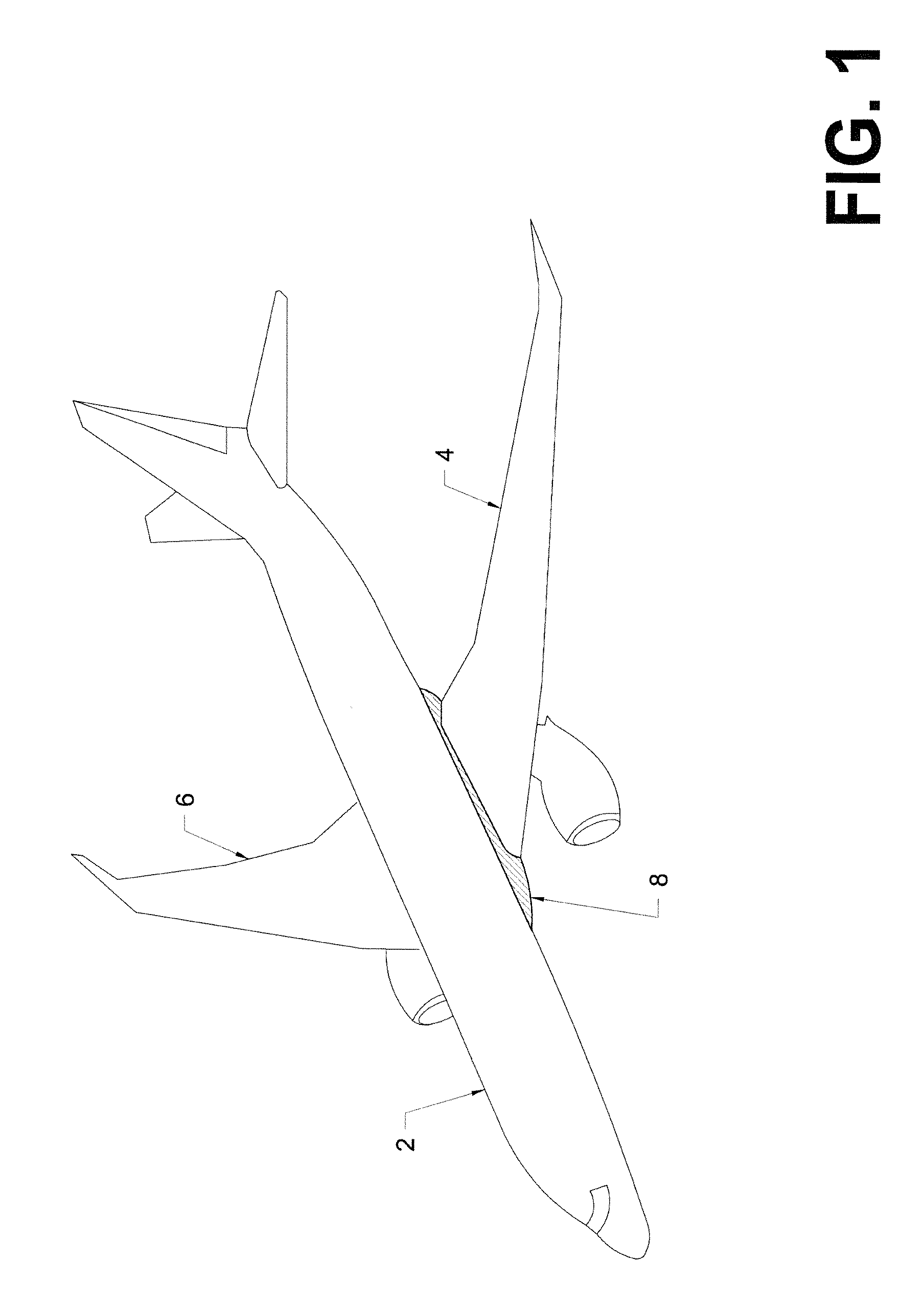
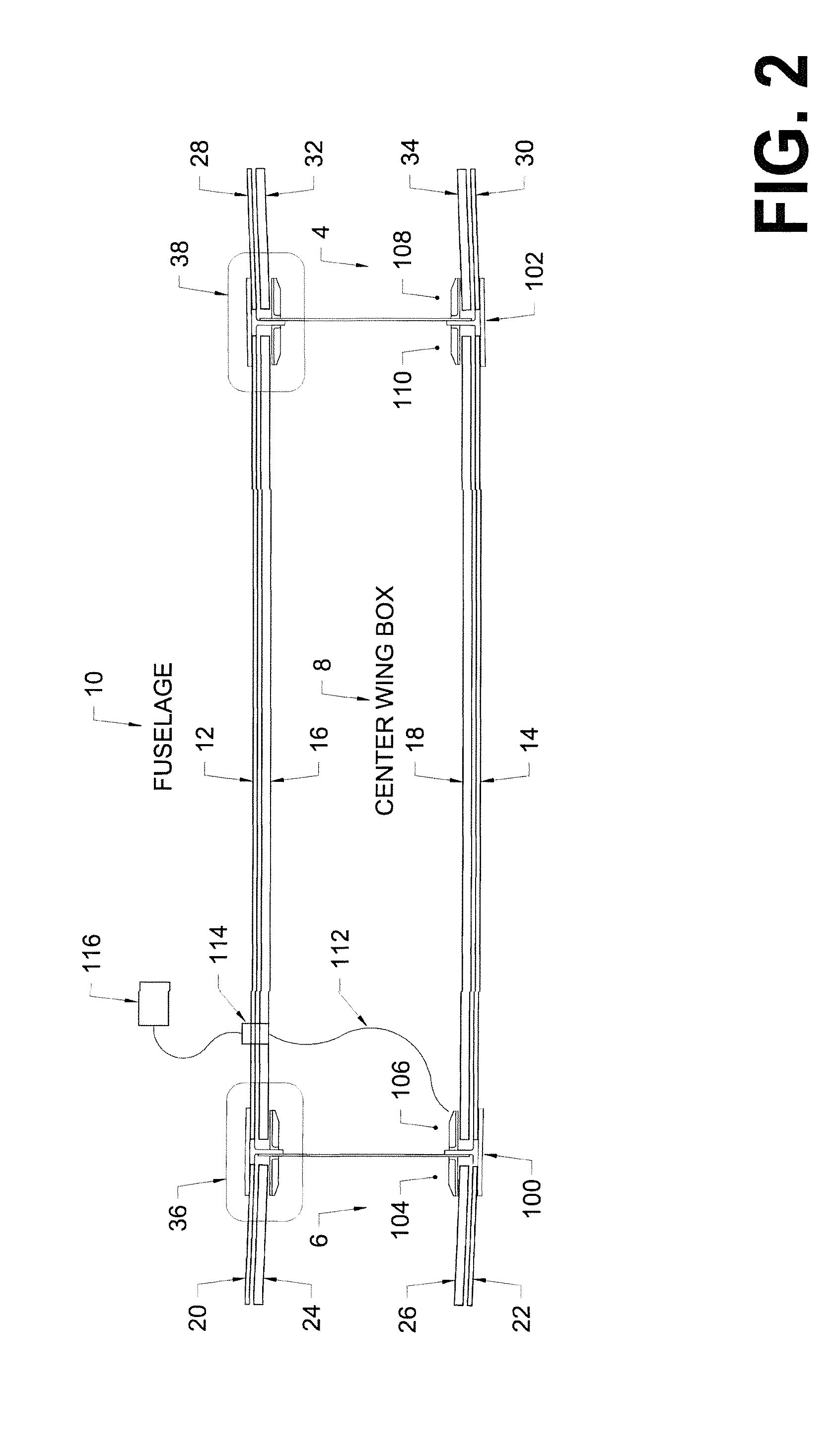
[0120]The fiber-reinforced wings and wing boxes of Boeing 787's are described very well in an article in The Seattle Times, dated Jul. 30, 2009, entitled “Double trouble for Boeing 787 wing” by Dominic Gates, that appears on the front page and on A8, an entire copy of which is incorporated herein by reference. That artic...


PUM


Abstract

Methods and apparatus are described to detect, measure, and determine the presence of unknown Groundloop currents flowing through unidentified circuit pathways within the wiring system distributed within a portion of a fuselage of an airplane substantially made from fiber-reinforced composite materials to avoid catastrophic failures of the electrical system within such an airplane.

Description

PRIORITY CLAIMED FROM RECENT U.S. PROVISIONAL PATENT APPLICATIONS[0001]Applicant claims priority for this application to U.S. Provisional Patent Application Ser. No. 62 / 070,130, filed on Aug. 15, 2014, that is entitled “Proposed Modifications of Main and APU Lithium-Ion Battery Assemblies on the Boeing 787 to Prevent Fires: Add One Cell, Eliminate Groundloops, and Monitor Each Cell with Optically Isolated Electronics—Part 5”, an entire copy of which is incorporated herein by reference. (PPA-105)[0002]Applicant claims priority for this application to U.S. Provisional Patent Application Ser. No. 62 / 070,585, filed on Aug. 29, 2014, that is entitled “Proposed Modifications of Main and APU Lithium-Ion Battery Assemblies on the Boeing 787 to Prevent Fires: Add One Cell, Eliminate Groundloops, and Monitor Each Cell with Optically Isolated Electronics—Part 6”, an entire copy of which is incorporated herein by reference. (PPA-106)[0003]Applicant also claims priority for this application to t...

Claims


Application Information

Patent Timeline
Patent Type & Authority Applications(United States)
IPC IPC(8): B64F5/00G01R31/00
CPCG01R31/008B64F5/0045B64F5/60
Inventor VAIL, III, WILLIAM BANNINGSKERL, TOMISLAVSCHWINBERG, PAUL B.MOMII, STEVEN T.
Owner SMART DRILLING & COMPLETION
Why Eureka
Try Eureka