Device for Assessing Extent of Degradation of Secondary Battery

a secondary battery and degradation technology, applied in battery/fuel cell control arrangement, instruments, transportation and packaging, etc., can solve the problems of difficult to estimate the ocv at that time point, and it is not possible to measure the ocv directly, so as to determine the extent of degradation of the secondary battery

Inactive Publication Date: 2015-12-03
HITACHI VEHICLE ENERGY
View PDF12 Cites 19 Cited by
  • Summary
  • Abstract
  • Description
  • Claims
  • Application Information

AI Technical Summary

Benefits of technology

[0016]According to the present invention, it is possible to determine the extent of degradation of a secondary battery in an accurate manner by obtaining the charge capacities of the secondary battery over a predetermined interval, even while the secondary battery is being used, in other words even while some device is operating.

Problems solved by technology

Accordingly it is necessary to measure the OCV accurately in order to obtain an accurate SOC, but, when a large current is flowing in the secondary battery, it is not possible to measure the OCV directly due to the influence of the voltage across the resistance possessed by the secondary battery, and moreover, in a state in which a current is flowing, it is difficult to estimate the OCV at that time point.

Method used


Image

  • Device for Assessing Extent of Degradation of Secondary Battery
  • Device for Assessing Extent of Degradation of Secondary Battery
  • Device for Assessing Extent of Degradation of Secondary Battery

Examples


embodiment # 1

Embodiment #1

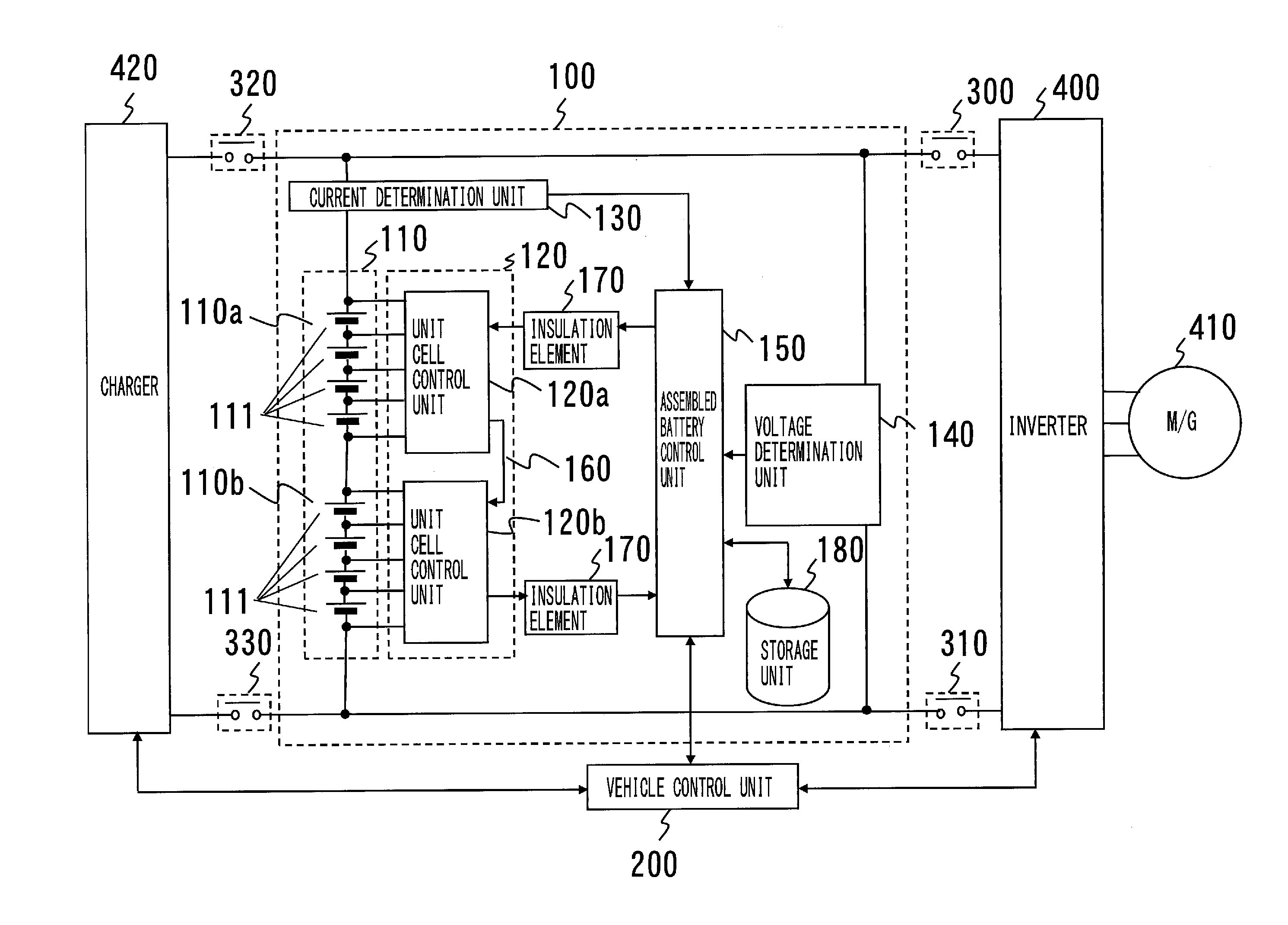
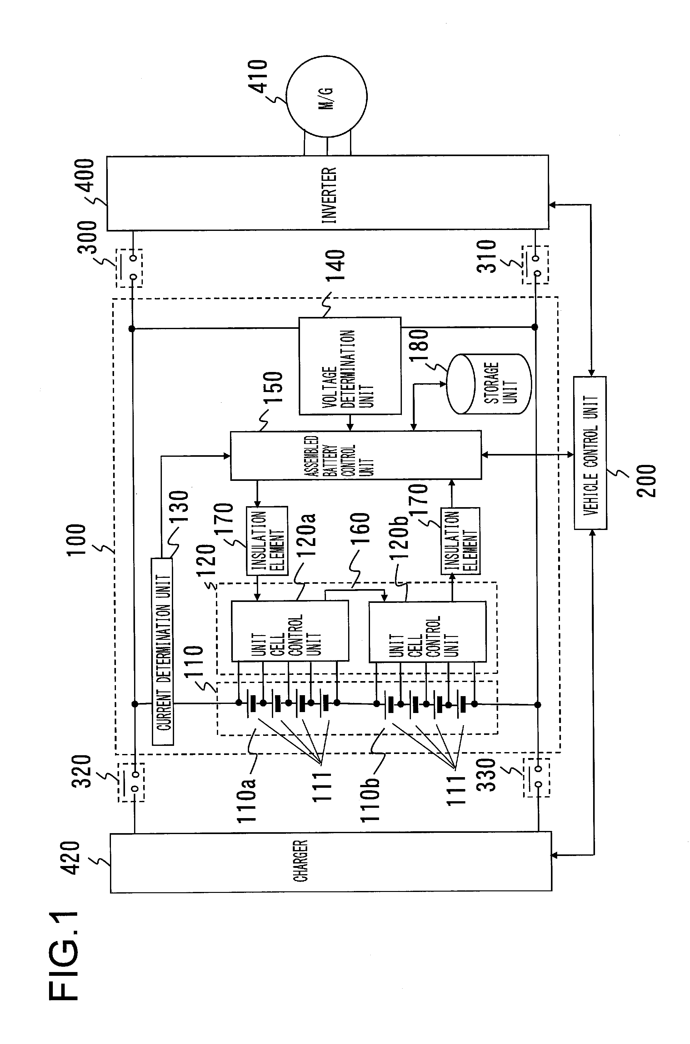
[0025]FIG. 1 is a block diagram showing a battery system 100 according to an embodiment of the present invention and its surrounding circuit structure. This battery system 100 is connected to a vehicle control unit 200, and the vehicle control unit 200 controls relays 300 and 310 and thereby connects the battery system 100 to an inverter 400. Moreover, the vehicle control unit 200 controls relays 320 and 330 and thereby connects the battery system 100 to a charger 420.

[0026]The battery system comprises an assembled battery 110, a unit cell control section 120, a current determination (detection) unit 130, a voltage determination (detection) unit 140, an assembled battery control unit 150, and a storage unit 180.

[0027]The assembled battery 110 is a secondary battery comprising unit cell groups 110a and 110b, with each of the unit cell groups 110a and 110b comprising a plurality of unit cells 111.

[0028]This assembled battery 110 is built by electrically connecting in seri...

embodiment # 2

Embodiment #2

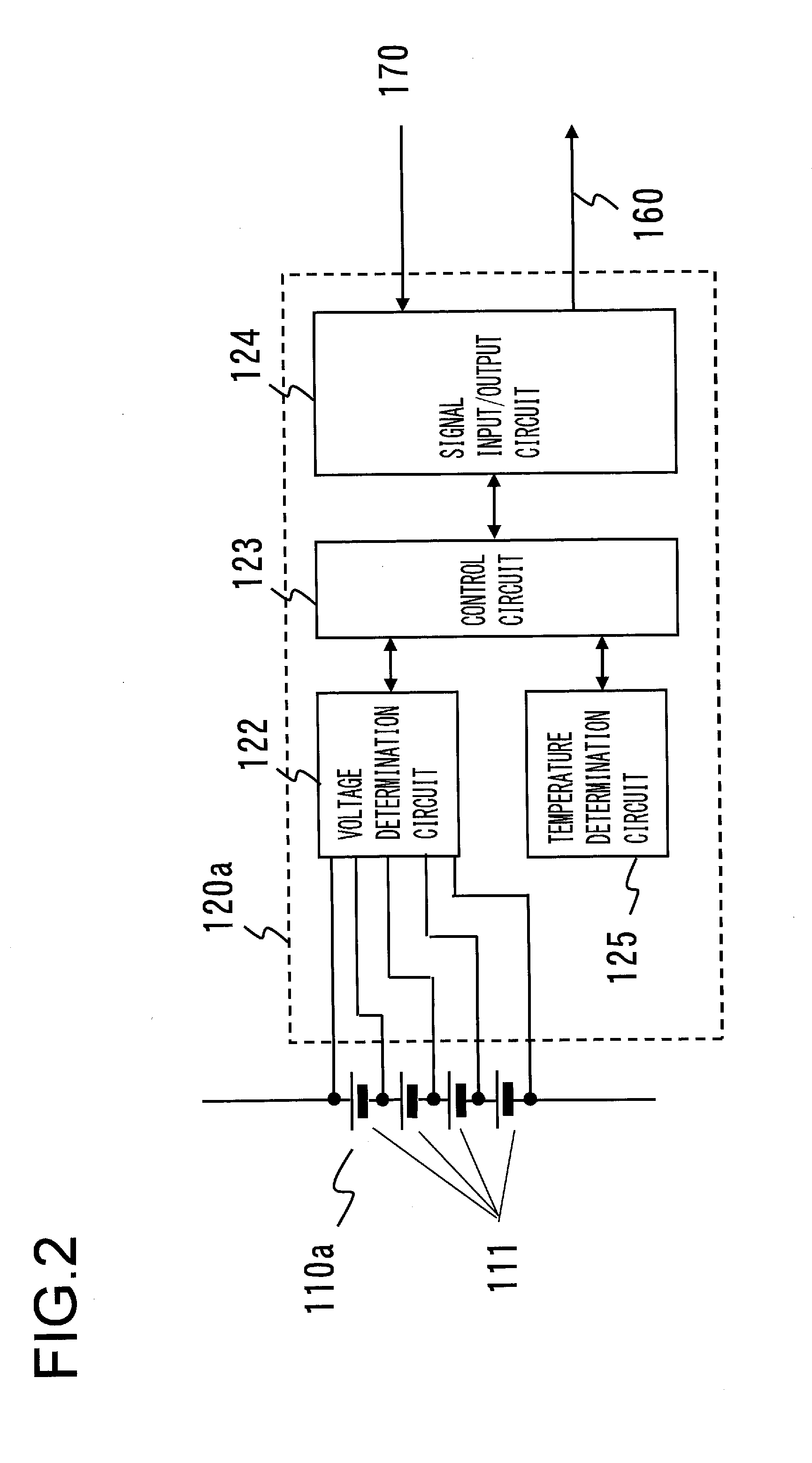
[0060]Next, a second embodiment of the present invention will be explained. Since a block diagram showing the circuit structure of the battery system 100 according to this second embodiment and of its surrounding circuitry would be the same as FIG. 1 and a block diagram showing the circuit structure of the unit cell control unit 120a would be the same as FIG. 2, accordingly such block diagrams and explanation thereof are omitted.

[0061]Next, the operation according to this second embodiment of the present invention for determining the extent of degradation of a secondary battery will be explained with reference to FIG. 4.

[0062]FIG. 4 is a flow chart for this determination of the extent of degradation of a secondary battery. During propulsion of the vehicle, the processing operations shown in this flow chart are repeatedly executed by the assembled battery control unit 150 continuously or upon a predetermined cycle; and moreover, to steps that perform the same processing ...

embodiment # 3

Embodiment #3

[0068]Next, a third embodiment of the present invention will be explained. Since a block diagram showing the circuit structure of the battery system 100 according to this third embodiment and its surrounding circuitry would be the same as FIG. 1 and a block diagram showing the circuit structure of the unit cell control unit 120a would be the same as FIG. 2, accordingly such block diagrams and explanation thereof are omitted.

[0069]Now, the operation according to this third embodiment of the present invention for determining the extent of degradation of a secondary battery will be explained with reference to FIG. 5.

[0070]FIG. 5 is a flow chart for this determination of the extent of degradation of a secondary battery. During propulsion of the vehicle, the processing operations shown in this flow chart are repeatedly executed by the assembled battery control unit 150 continuously or upon a predetermined cycle; and moreover, to steps that perform the same processing operati...


PUM


Abstract

A device for assessing an extent of degradation of a secondary battery, includes: a determination unit that determines whether or not a value of current flowing in the secondary battery is less than a predetermined value; a first voltage measurement unit that takes a time point at which it is determined by the determination unit that the value of the current is less than the predetermined value as being a start time point of a specific interval, and that measures a first battery voltage of the secondary battery at the start time point; a first charge amount calculation unit that obtains a first charge amount corresponding to the secondary battery based upon the measured first battery voltage; a second voltage measurement unit that, after the first battery voltage has been measured by the first voltage measurement unit, takes a time point at which it is determined by the determination unit that the value of the current is less than the predetermined value as being an end time point of the specific interval, and that measures a second battery voltage of the secondary battery at the end time point; a second charge amount calculation unit that obtains a second charge amount corresponding to the secondary battery based upon the measured second battery voltage; an integrated current amount calculation unit that obtains an integrated amount of the current flowing in the secondary battery during the specific interval; and a charge capacity calculation unit that obtains a difference between the first charge amount and the second charge amount, and that calculates a charge capacity by dividing the integrated amount of the current by the difference.

Description

TECHNICAL FIELD[0001]The present invention relates to a device for assessing the extent of degradation of a secondary battery, that assesses the extent of degradation of a secondary battery.BACKGROUND ART[0002]Generally a secondary battery that can be charged and discharged, such as is represented by a lithium ion battery or a nickel-hydrogen battery, deteriorates due to repeatedly being charged and discharged, and, as compared with its initial charge capacity, its charge capacity progressively decreases.[0003]With a device that employs a secondary battery, it is necessary to ascertain the present charge capacity of the secondary battery accurately in order to estimate the time period that the device can be operated, and in order to determine the lifetime of the secondary battery and to be certain of the timing at which it should be exchanged for a new secondary battery. In such a device, a system is provided that compares the present charge capacity and the initial charge capacity ...

Claims


Application Information

Patent Timeline
Patent Type & Authority Applications(United States)
IPC IPC(8): G01R31/36
CPCG01R31/3679G01R31/3658G01R31/3624B60L2240/545B60L2240/547B60L2240/80B60L2260/44G01R31/3828B60L58/16B60L58/12G01R31/392G01R31/3842G01R31/396H02J7/0048Y02T10/70H02J7/0013H02J7/005
Inventor IGARASHI, NAOYUKIOHKAWA, KEIICHIRO
Owner HITACHI VEHICLE ENERGY
Why Eureka
Try Eureka