Structure for mounting hall effect sensor of motor

a technology for hall effect sensors and motors, which is applied in the direction of galvano-magnetic hall-effect devices, windings, instruments, etc., can solve the problems of difficult positioning of control circuit boards and unreliable installation, and achieve excellent heat dissipation, simple structure, and high integral strength of front end covers.

Active Publication Date: 2015-12-03
ZHONGSHAN BROAD OCEAN
View PDF6 Cites 8 Cited by
  • Summary
  • Abstract
  • Description
  • Claims
  • Application Information

AI Technical Summary

Benefits of technology

[0026]6) The inner side panel is protruded upwards from the inner edge of the top surface of each tooth. The left base and the right base are connected to corresponding inner side panels, respectively. The structure is simple. The integrity of the left supporting column, the left base, and the inner side panel and the integrity of the right supporting column, the right base, and the inner side panel are improved, and the installation is much firm.
[0027]7) The upper bearing seat. The bearing cavity is disposed in the upper bearing seat. The outer wall of the upper bearing seat is provided with the first stiffeners. The bottom wall of the bearing cavity is convex downwards from the bottom surface of the front end cover and forms the lower bearing seat. The outer wall of the lower bearing seat is provided with the second stiffeners. The structure is simple, the integral strength of the front end cover is high, the heat dissipation is excellent, the service lives of the bearing and the motor are improved, and the reliability of the structure is high.
[0028]8) The first stiffeners are radially disposed on the top surface of the front end cover. The plurality of through holes for heat dissipation is radially arranged between two adjacent first stiffeners. The through holes for heat dissipation are able to improve the heat dissipation capacity of the front end cover as well as decrease the noise produced during the operation of the motor.
[0029]9) The annular boss is disposed on the outer edge of the top surface of the front end cover, and two ends of the first stiffeners are connected to the outer wall of the upper bearing seat and the annular boss. The outer edge of the front end cover protrudes the mounting feet, two sides of the mounting feet are provided with third stiffeners, and the third stiffeners are connected to the outer edge of the front end cover. The structure is simple, the integral strength of the front end cover is improved, and the service life thereof is prolonged.
[0030]10) The number of the mounting feet is four; the mounting feet are radially disposed on the outer edge of the front end cover. The outer edge of the front end cover between two adjacent mounting feet protrudes arc panels, and two sides of each arc panel are connected to the two adjacent mounting feet, so that the connection strength between the adjacent mounting feet are enhanced.
[0031]11) The rear end cover comprises: the rear bearing seat, and four supporting arms extended from the outer wall of the rear bearing seat. The four supporting arms are arranged in the pattern of the character “X”. Two mounting seats are symmetrically disposed at the outer edge of the top surface of the front end cover. Screws pass through the supporting arms and the stator assembly and are inserted into the mounting seats to tightly cooperate with screw nuts whereby fixing the front end cover and the rear end cover on two ends of the housing, respectively. The structure is simple, and the installation thereof is firm.

Problems solved by technology

However, such installation is unreliable, the control circuit board is difficult to position, and the Hall effect sensor tends to detach from the control circuit board.

Method used


Image

  • Structure for mounting hall effect sensor of motor
  • Structure for mounting hall effect sensor of motor
  • Structure for mounting hall effect sensor of motor

Examples


Embodiment Construction

[0049]For further illustrating the invention, experiments detailing a structure for mounting a Hall effect sensor of a motor are described below. It should be noted that the following examples are intended to describe and not to limit the invention.

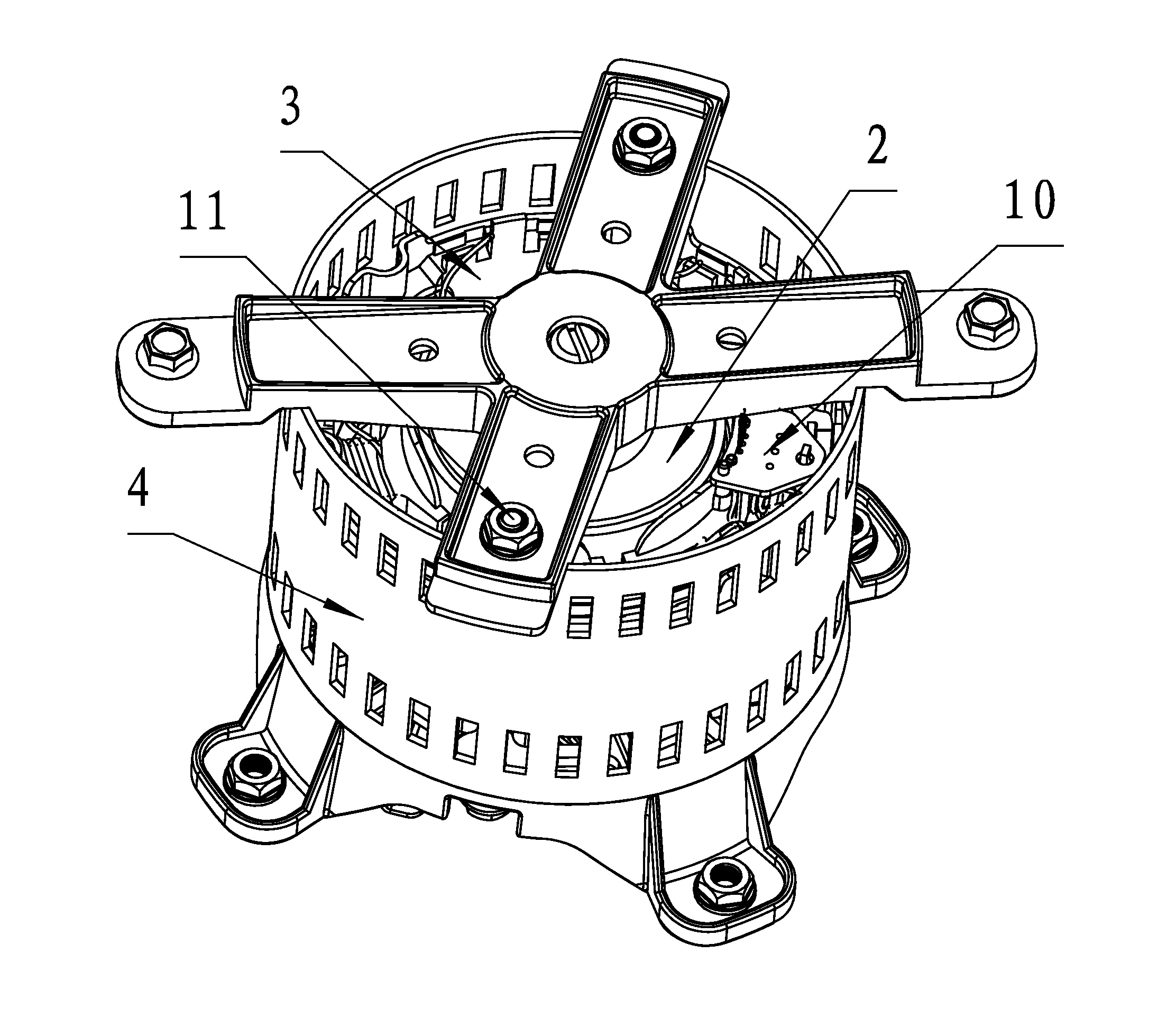
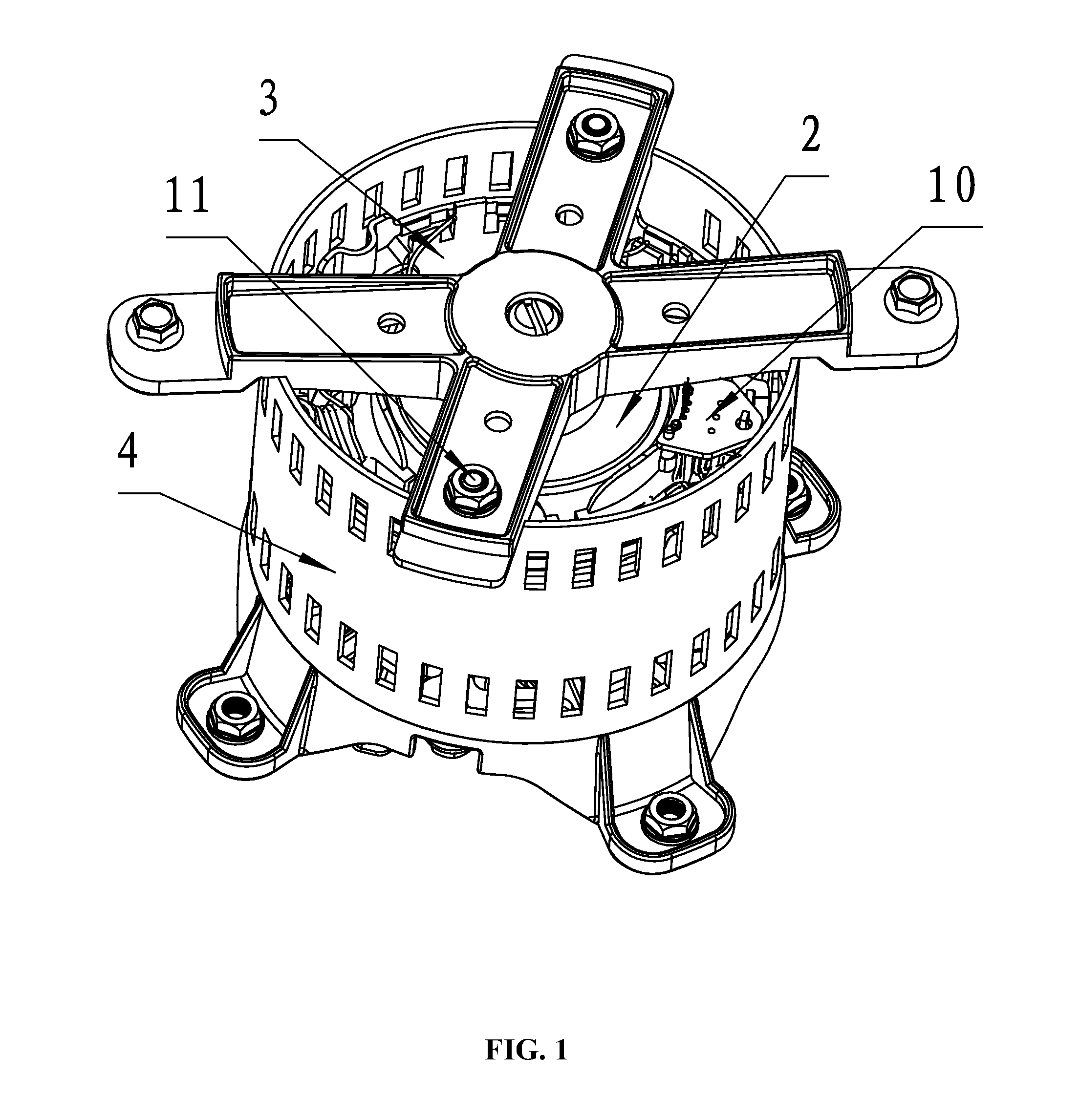
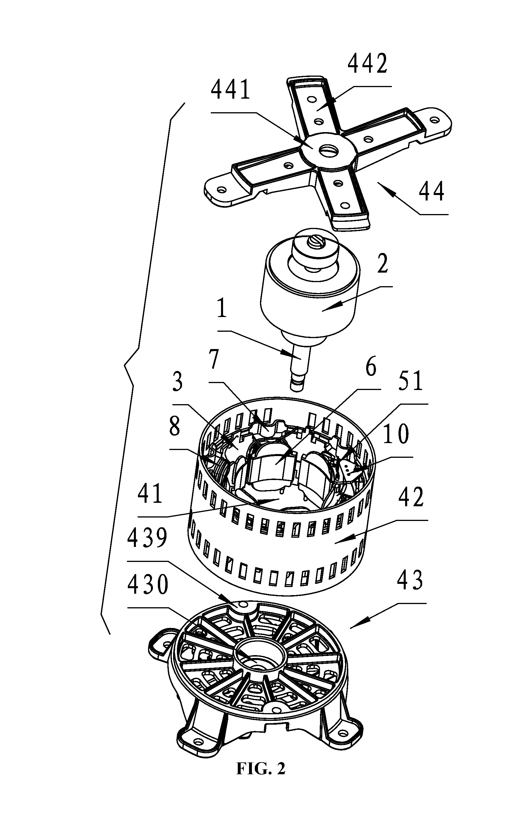
[0050]A structure for mounting a Hall effect sensor of a motor is illustrated in FIG. 1-16. The motor comprises: a rotating shaft 1, a rotor assembly 2, a stator assembly 3, a housing assembly 4, a Hall effect sensor 5. The rotor assembly 2 is disposed on the rotating shaft 1. The rotor assembly 2 is nested within the stator assembly 2. A cavity 41 is disposed in the middle of the housing assembly 4; and the rotor assembly 2 and the stator assembly 3 are mounted in the cavity 41 of the housing assembly. The stator assembly 3 comprises: an iron core 6, an end insulation 7, and coil windings 8. The end insulation 7 is disposed on an end part of the iron core 6, and the coil windings 8 are wound on the end insulation 7. The end insulation 7 ...


PUM


Abstract

A structure for mounting a Hall effect sensor, the structure including: a mounting bracket, a mounting plate, a left supporting column, a right supporting column, and a first supporting column. The left supporting column and the right supporting column are protruded upwards from top surfaces of two adjacent teeth at the inner side of a certain winding slot, respectively. The first supporting column is protruded upwards from the top surface of the circular yoke at the outer side of the winding slot. The mounting plate is disposed on top surfaces of the first supporting column, the left supporting column, and the right supporting column. The mounting bracket is installed at the bottom of the mounting plate. The Hall effect sensor is installed in the mounting bracket.

Description

CROSS-REFERENCE TO RELATED APPLICATIONS[0001]This application is a continuation-in-part of International Patent Application No. PCT / CN2014 / 074172 with an international filing date of Mar. 27, 2014, designating the United States, now pending, and further claims priority benefits to Chinese Patent Application No. 201320705788.7 filed Nov. 8, 2013, and to Chinese Patent Application No. 201320779542.4 filed Nov. 30, 2013. The contents of all of the aforementioned applications, including any intervening amendments thereto, are incorporated herein by reference. Inquiries from the public to applicants or assignees concerning this document or the related applications should be directed to: Matthias Scholl P.C., Attn.: Dr. Matthias Scholl Esq., 245 First Street, 18th Floor, Cambridge, Mass. 02142.BACKGROUND OF THE INVENTION[0002]1. Field of the Invention[0003]The invention relates to a structure for mounting a Hall effect sensor of a motor.[0004]2. Description of the Related Art[0005]Typical...

Claims


Application Information

Patent Timeline
Patent Type & Authority Applications(United States)
IPC IPC(8): G01R33/07G01R33/00
CPCG01R33/0047G01R33/072G01R33/07H02K3/522H02K5/00H02K5/15H02K11/215
Inventor WANG, XIONGCHENGFU, GUIWENYU, YUEQIANG
Owner ZHONGSHAN BROAD OCEAN
Why Eureka
Try Eureka