Adjustable passive flow regulator

a flow regulator and adjustable technology, applied in the direction of flow monitors, wound drains, functional valve types, etc., can solve the problems of complicated and expensive fabrication of such devices, affecting the accuracy level, and affecting the flow of fluid through, so as to achieve the effect of increasing the fluidic resistan

Inactive Publication Date: 2015-12-03
DEBIOTECH SA
View PDF1 Cites 6 Cited by
  • Summary
  • Abstract
  • Description
  • Claims
  • Application Information

AI Technical Summary

Benefits of technology

[0025]When a pressure applied to the upper face is larger than a predefined threshold value, the flexible membrane is able to come into contact with at least a part of said substrate. The parts of said substrate and / or said membrane may comprise said through holes defining thereby a valve which may increase the fluidic resistance and may hinder a fluid from flowing through said through holes.

Problems solved by technology

A known problem of these passive devices is that the drug flow rate to a delivery location, which may be a patient's body for instance, may vary as a function of the amount of drug remaining in the reservoir as far as the pressure in the reservoir depends on this amount.
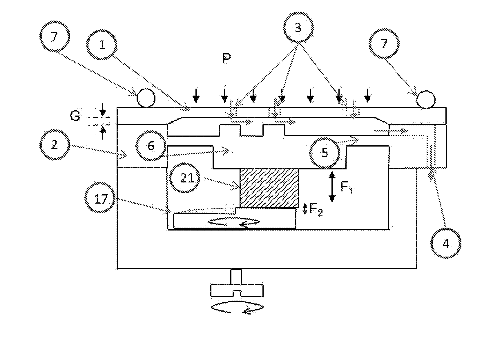
As the membrane would come into contact with the substrate in the region of its central through hole, this would occlude the latter and result in hindering a fluid from flowing through it.
However, fabrication of such a device is complicated and expensive.
Indeed, the substrate has to be etched according to a specific pattern, which is rather delicate regarding the accuracy level that has to be respected for the flow regulation to operate properly.
Thus, not only the manufacture of the substrate requires specific extra-steps, but also these steps are further delicate to carry out.
Depending on the dimensions of the device, specific materials such as Sal is to be used for manufacture of the substrate, which is still more expensive.
The large contact area between the membrane and the substrate at high pressure can be problematic since any particle in this area will induce a leakage.
Complex fluidic simulations of such device are necessary to estimate the spiral shape and to take into account the flow restriction outside of the channel, making any design change difficult.
Both theoretical and experimental data reported show that a perfectly steady rate cannot be achieved since the flow resistance should increase with the applied pressure in a linear manner and the change of the cross-section of the channel is strongly non-linear.
This non-linearity is not compensated by the use of a spiral channel.
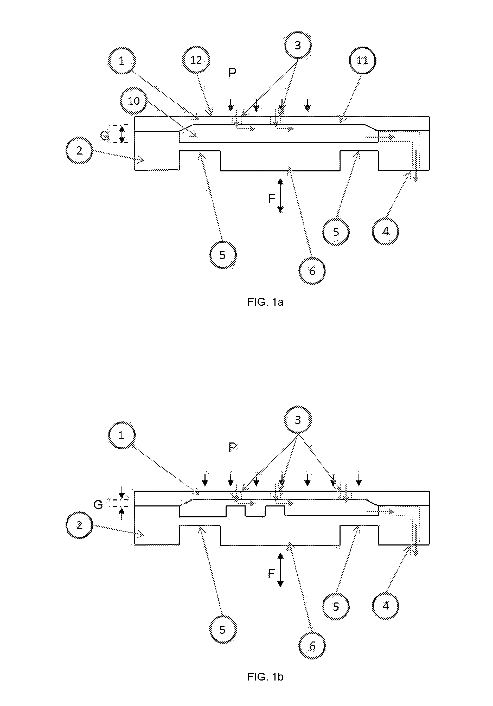
As the pressure drop increases, the valve membrane deforms upward and constricts the main channel, leading to an increase of the fluidic resistance with applied pressure and thus to nonlinearity for Newtonian fluids.
The presence of dead-ends for such devices makes the priming difficult.
But the main drawback of such devices is the flow-rate accuracy.
Moreover, the fact that the reservoir pressure applies directly on both sides of the membrane makes necessary the use of a small gap between the pillar and the membrane at any pressure otherwise the device do not regulate the flow.
Relative machining tolerances for this gap are also difficult to achieve.
But, after its manufacturing, this device cannot be adjusted as necessary to suit the particular needs of patient.
Clinical experience has proven that this principle of shunting is not an ideal solution.
Sudden rises of the ICP, e.g. due to change of position, physical exercise, or pathological pressure waves result in excessive CSF drainage.
Several reports in the literature (Aschoff et al., 1995) point at problems due to this over-drainage, and especially the pronounced narrowing of the ventricles has been pointed out as being the main factor leading to malfunctioning of the implanted shunting device.
The reason is that the ventricular walls may collapse around the ventricular CSF shunt device, and particles (cells, debris) may intrude into the shunt device.
But one of the major drawbacks of theses valves lies in their lack of adjustment means.
Unfortunately, the characteristics of the valve need to be adapted to each patient as a function of the natural characteristics of the patient's organism, and for any given patient, the characteristics of the valve need to be modified over time as a function of the way the disease evolves.
However, due to the elastomeric properties of the diaphragm material, maintenance of the implanted valve may be required.
Further, flow rate adjustment of this adjustable valve after implantation may require a surgical procedure.
Although the Watanabe device permits flow rate control palpably through the scalp and thus, without surgical intervention, patient and / or physician attention to the valve settings is required.
Several reports in the literature [Aschoff A et al., Conference Shunt Technology, Center of Devices and Radiological Health—Food and Drug Administration, Bethesda, Md., 8 January 1999] point at problems due to this overdrainage, and especially the pronounced narrowing of the ventricles has been pointed out as being the main factor leading to malfunctioning of the implanted shunting device.
The reason is that the ventricular walls may collapse around the ventricular CSF shunt device, and particles (cells, debris) may intrude into the shunt device.
These devices are therefore very sensitive to particles and relative machining tolerances for this gap are also difficult to achieve.
Several devices cannot be adjusted or are not easily adjustable.
Thus, the major drawbacks of these valves lies in their lack of accuracy, their adjustable means, their sensitivity to particles, their range of use and / or their sensitivity to the temperature.

Method used


Image

  • Adjustable passive flow regulator
  • Adjustable passive flow regulator
  • Adjustable passive flow regulator

Examples


Embodiment Construction

[0082]As used in this specification and the appended claims, any direction referred to herein, such as “top”, “bottom”, “left”, “right”, “upper”, “lower”, and other directions or orientations are described herein for clarity in reference to the figures and are not intended to be limiting of an actual device or system. Devices and systems described herein may be used in a number of directions and / orientations.

[0083]As used in this specification and the appended claims, the term “or” is generally employed in its sense including “and / or” unless the content clearly dictates otherwise.

[0084]As used herein, “have”, “having”, “include”, “including”, “comprise”, “comprising” or the like are used in their open ended sense, and generally mean “including, but not limited to”.

[0085]The invention is set forth and characterized in the independent claims, while the dependent claims describe other characteristics of the invention.

[0086]According to an embodiment but not limited to, the FIG. 1 show ...


PUM


Abstract

An adjustable passive flow regulator may be used in the field of drug delivery (liquid or gaseous, e.g. for pain management) or for draining cerebrospinal fluid (CSF) for hydrocephalus patient.

Description

FIELD OF INVENTION[0001]The present invention is related to an adjustable passive flow regulator which may be used in the field of drug delivery (liquid or gaseous, e.g. for pain management) or for draining cerebrospinal fluid (CSF) for hydrocephalus patient.STATE OF THE ART[0002]Passive drug infusion devices, in contrast to active ones, do not rely on a pump to deliver a drug but rather on a pressurized drug reservoir. A known problem of these passive devices is that the drug flow rate to a delivery location, which may be a patient's body for instance, may vary as a function of the amount of drug remaining in the reservoir as far as the pressure in the reservoir depends on this amount. Such passive devices are thus usually provided with a fluid flow regulator to ensure that the drug flow rate is as constant as possible with respect to the amount of drug remaining in the reservoir.[0003]An example of such a passive drug flow regulator is available by the Applicant under the register...

Claims


Application Information

Patent Timeline
Patent Type & Authority Applications(United States)
IPC IPC(8): G05D7/01
CPCY10T137/7922G05D7/0113A61M5/168F16K99/00A61M5/16881A61M27/006
Inventor CHAPPEL, ERIC
Owner DEBIOTECH SA
Why Eureka
Try Eureka