
Impact resistant OLED devices

a technology of impact resistance and oled, which is applied in the direction of solid-state devices, semiconductor devices, thermoelectric devices, etc., can solve the problems of easy damage to glass layers closer to the impact surface, breakage of 34′′ thick normal glass plates, etc., and achieve high efficiency

Active Publication Date: 2015-12-03
UNIVERSAL DISPLAY
View PDF21 Cites 5 Cited by
  • Summary
  • Abstract
  • Description
  • Claims
  • Application Information

AI Technical Summary

Benefits of technology

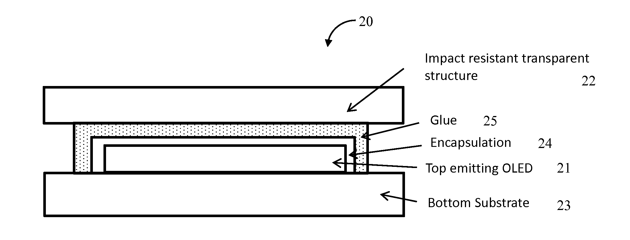
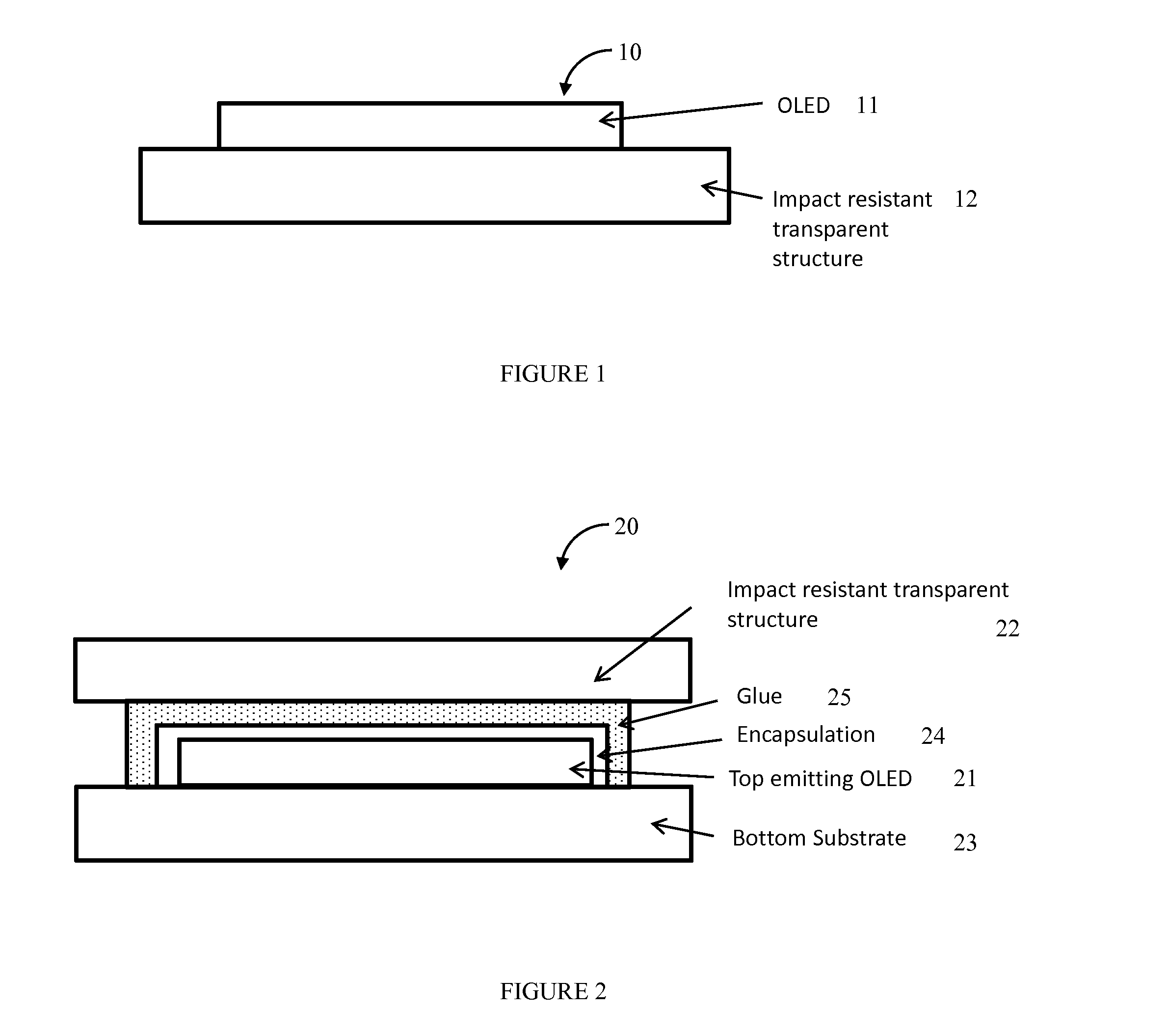
This patent describes a system and method for making high-efficiency OLED devices. These devices can be built directly on a strong and transparent layer, or attached to other materials like a glass or energy-absorption layer. The transparent layer provides impact resistance to the OLED, so it can withstand impact from objects. The light from the OLED is transmitted through the transparent layer, and its impact resistance prevents any damage to the device.

Problems solved by technology

This generally causes breakage of ¾″ thick normal glass plate.
However, it is not preferred to use traditional bullet proof glass as display substrate material because of optical effects.
The glass layers closer to the impact surface can easily get damaged.
Although this effectively slows down a bullet, it does generate many cracks, which may not be acceptable for optical reasons in certain cases because the densely distributed cracks will make the image not recognizable.

Method used


Image

  • Impact resistant OLED devices
  • Impact resistant OLED devices
  • Impact resistant OLED devices

Examples


Embodiment Construction

[0023]Generally, an OLED comprises at least one organic layer disposed between and electrically connected to an anode and a cathode. When a current is applied, the anode injects holes and the cathode injects electrons into the organic layer(s). The injected holes and electrons each migrate toward the oppositely charged electrode. When an electron and hole localize on the same molecule, an “exciton,” which is a localized electron-hole pair having an excited energy state, is formed. Light is emitted when the exciton relaxes via a photoemissive mechanism. In some cases, the exciton may be localized on an excimer or an exciplex. Non-radiative mechanisms, such as thermal relaxation, may also occur, but are generally considered undesirable.

[0024]The initial OLEDs used emissive molecules that emitted light from their singlet states (“fluorescence”) as disclosed, for example, in U.S. Pat. No. 4,769,292, which is incorporated by reference in its entirety. Fluorescent emission generally occur...


PUM


Abstract

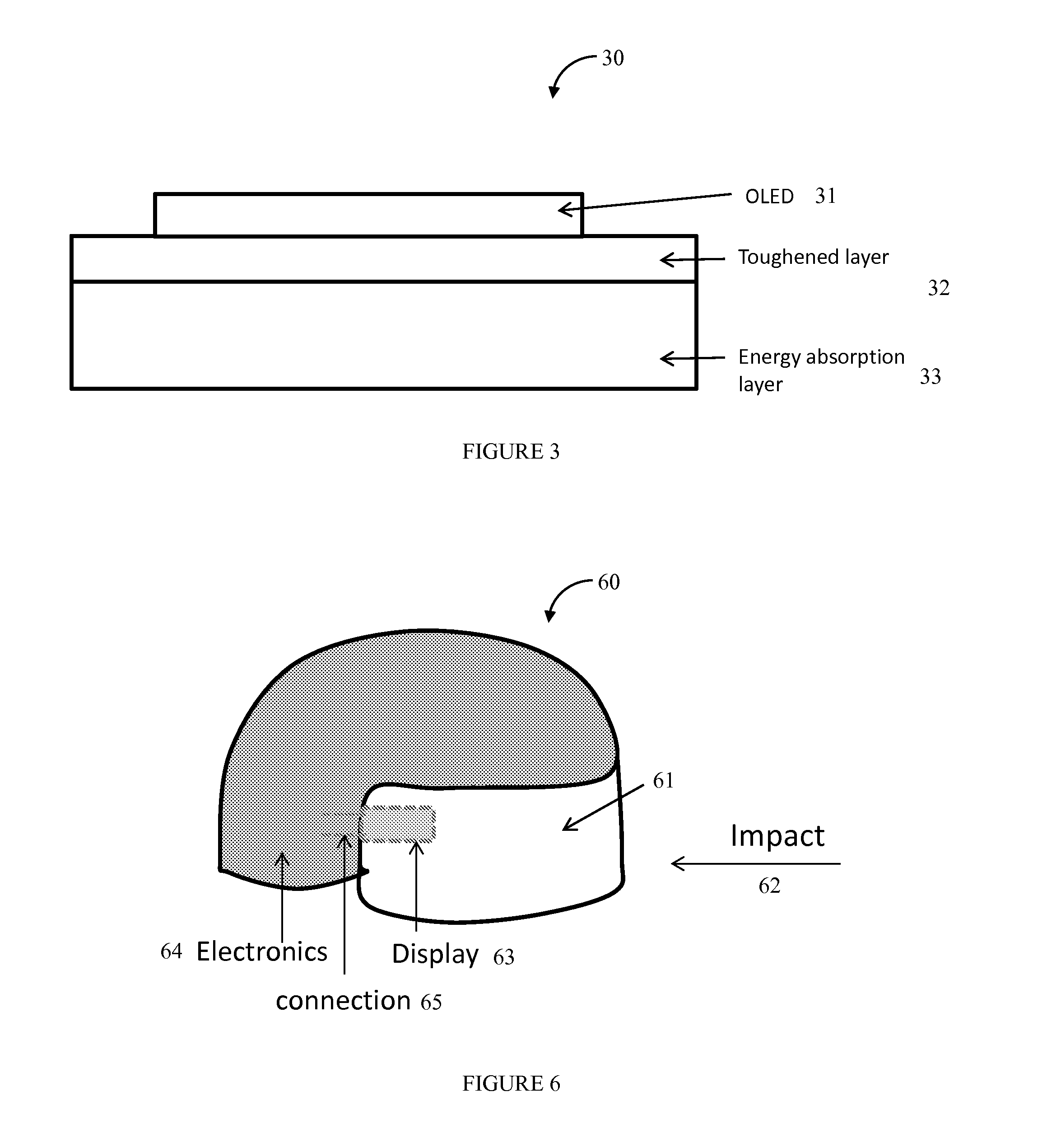
A system and method for the fabrication of high efficiency OLED devices and more specifically, the fabrication of OLED panels optically coupled with impact resistant, transparent structures which permit operation of the OLED panel while providing impact resistance. The OLED device can be built directly on an impact resistant transparent structure, or attached to an impact resistant transparent structure after it is built on other types of substrate. The impact resistant transparent structure can be a toughened layer, such as a glass layer, an energy absorption layer, such as Polycarbonate (PC), or a combination of both. The OLED device is configured to transmit light through the impact resistant transparent structure to the viewer, and the impact resistant transparent structure provides impact resistance for the OLED from the force of any impacting object.

Description

CROSS-REFERENCE TO RELATED APPLICATIONS[0001]This application claims the benefit under 35 U.S.C. 119(e) of a U.S. provisional patent application of Siddharth Harikrishna Mohan et al., entitled “Hermetically Sealed Isolated OLED Pixels”, Ser. No. 61 / 970,937, filed Mar. 27, 2014, the entire contents of said application being incorporated herein by reference.FIELD OF THE INVENTION[0002]The present invention relates generally to the fabrication of high efficiency OLED devices and more specifically, to the fabrication of OLED panels optically coupled with impact resistant, transparent structures which permit operation of the OLED panel while providing impact resistance.BACKGROUND[0003]In many applications, an electronic device needs to survive extreme external forces. This can range from devices being dropped on the floor, to sustaining impact from various projectiles in harsh environments that may include high speed collisions with sharp, solid debris which are characteristic of combat,...

Claims


Application Information

Patent Timeline
Patent Type & Authority Applications(United States)
IPC IPC(8): H01L51/52H01L51/56H01L27/32H01L51/00H10K99/00
CPCH01L51/5253H01L51/5246H01L27/3246H01L51/56H01L51/0097Y02E10/549H10K77/111H10K59/8722H10K50/841H10K50/8426
Inventor PREMUTICO, MAUROMA, RUIQING
Owner UNIVERSAL DISPLAY
Learn More