Cage rotor of an asynchronous machine

a cage rotor and asynchronous machine technology, applied in the field of cage rotors of asynchronous machines, can solve the problem that the material is not suitable for high centrifugal stress, and achieve the effect of increasing the strength of the material

Active Publication Date: 2015-12-03
SIEMENS AG
View PDF18 Cites 14 Cited by
  • Summary
  • Abstract
  • Description
  • Claims
  • Application Information

AI Technical Summary

Benefits of technology

[0033]If the head area of the grooves of the rotor is cast with aluminum alloy instead of Al99.5, because of the higher strength of this material, the casting compound is prevented from flowing out of the groove. Thus almost ope

Problems solved by technology

In such cases irregular expansions occur on the short circuit ring caused by centrifugal forces, which become noticeable as non-recoverable changes and to this extent

Method used


Image

  • Cage rotor of an asynchronous machine
  • Cage rotor of an asynchronous machine
  • Cage rotor of an asynchronous machine

Examples


Embodiment Construction

[0040]Throughout all the figures, same or corresponding elements may generally be indicated by same reference numerals. These depicted embodiments are to be understood as illustrative of the invention and not as limiting in any way. It should also be understood that the figures are not necessarily to scale and that the embodiments are sometimes illustrated by graphic symbols, phantom lines, diagrammatic representations and fragmentary views. In certain instances, details which are not necessary for an understanding of the present invention or which render other details difficult to perceive may have been omitted.

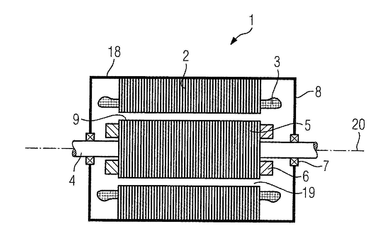
[0041]Turning now to the drawing, and in particular to FIG. 1, there is shown in a basic diagram a longitudinal section of an dynamo-electric machine, which is designed as an asynchronous motor, wherein a housing 18, which accommodates end shields 8, holds a shaft 4 to which a rotor or armature 5 with its laminated core is connected in a torsion-proof manner. The rotor or th...


PUM

PropertyMeasurementUnit
Speedaaaaaaaaaa
Mechanical strengthaaaaaaaaaa
Electrical conductivityaaaaaaaaaa

Abstract

A cage rotor of a rotary asynchronous machine includes an axially laminated core having substantially axially extending grooves, at least one electrical conductor disposed in the grooves and composed of at least of two partial conductors constructed from materials having different electrical conductivities and different mechanical strengths, wherein the partial conductor made of the higher-strength material is disposed radially farther outwardly at least in sections of the groove, as viewed along the axial extent of the respective, and a short-circuit ring arranged on a respective end face side of the laminated core and electrically-conductively interconnecting the electrical conductors that are disposed in the respective grooves and protrude axially from the laminated core.

Description

CROSS-REFERENCES TO RELATED APPLICATIONS[0001]This application claims the priority of German Patent Application, Serial No. 10 2014 210 339.8, filed Jun. 2, 2014, pursuant to 35 U.S.C. 119(a)-(d), the content of which is incorporated herein by reference in its entirety as if fully set forth herein.BACKGROUND OF THE INVENTION[0002]The present invention relates to a cage rotor of an asynchronous machine with an axially laminated core having grooves running essentially axially, in which an electrical conductor is located which, with the electrical conductors in other grooves, embodies short circuit rings on the respective end face sides of the laminated core and thus forms a cage rotor.[0003]In asynchronous motors with cage rotors, which are employed in the higher speed range, the short circuit ring in particular proves to be a weak point on the rotor. In such cases irregular expansions occur on the short circuit ring caused by centrifugal forces, which become noticeable as non-recover...

Claims


Application Information

Patent Timeline
IPC IPC(8): H02K17/16H02K15/00
CPCH02K17/165Y10T29/49014H02K15/0012H02K3/02H02K17/20
Inventor BUTTNER, KLAUSKIRCHNER, KLAUSWARMUTH, MATTHIASWOLF, NICO
Owner SIEMENS AG
Why Eureka
Try Eureka