Fluidic circuits and related manufacturing methods

a technology of fluidic microcircuitry and manufacturing methods, applied in the direction of positive displacement liquid engines, machines/engines, laboratory glassware, etc., can solve the problems of insufficient disclosures to fully enable fluidic microcircuitry pumps and valves, and the general compatibility of silicon-based microelectromechanical structures with modern plastic devices

Active Publication Date: 2015-12-10
PERKINELMER HEALTH SCIENCES INC
View PDF5 Cites 30 Cited by
  • Summary
  • Abstract
  • Description
  • Claims
  • Application Information

AI Technical Summary

Benefits of technology

[0033]Sheets of diaphragm materials may be welded or tacked to a polymeric substrate using laser decoupage or hot nip roller decoupage, although laser decoupage has the advantage that a laser can be guided over the workpiece to make welds according to a programmable ...

Problems solved by technology

An unsolved problem is the ability to manufacture circuits in which the diaphragm material can be varied (e.g., breathable, chemically resistant, rupturable, elastomeric, inelastic, and so forth) according to the type or subtype of circuit element.
A second unsolved problem relates to the manufacturability of microcircuits having millimeter and sub-millimeter footprints.
Miniaturization has proven a benefit, favoring development of devices having a higher density of circuit components per unit area, but valves and diaphragms at a millimeter or sub-millimeter scale have been difficult to realize by current production methods.
Although miniature pumps were generically disclosed by Wilding (for example in U.S. Pat. Nos. 5,304,487 and 5,498,392), the disclosures themselves were not sufficient to fully enable fluidic microcircuitry pumps and valves.
Silicon-based microelectromechanical (MEMS) structures are not generally compatible with modern plastic devices.
In addition to delicacy of mechanical solenoid operation and need for fine adjustment, the membrane is subjected to great stresses with the risk of permanent stretch (i.e., permanent deformation or pinching past its yield point).
By virtue of the con...

Method used


Image

  • Fluidic circuits and related manufacturing methods
  • Fluidic circuits and related manufacturing methods
  • Fluidic circuits and related manufacturing methods

Examples


Embodiment Construction

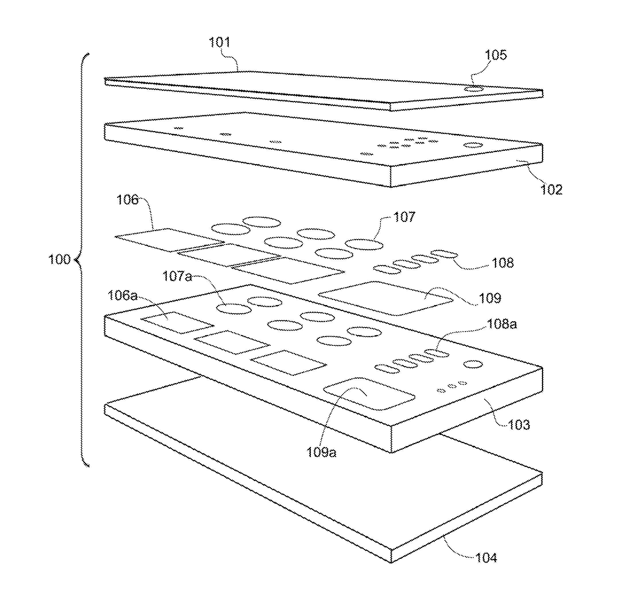
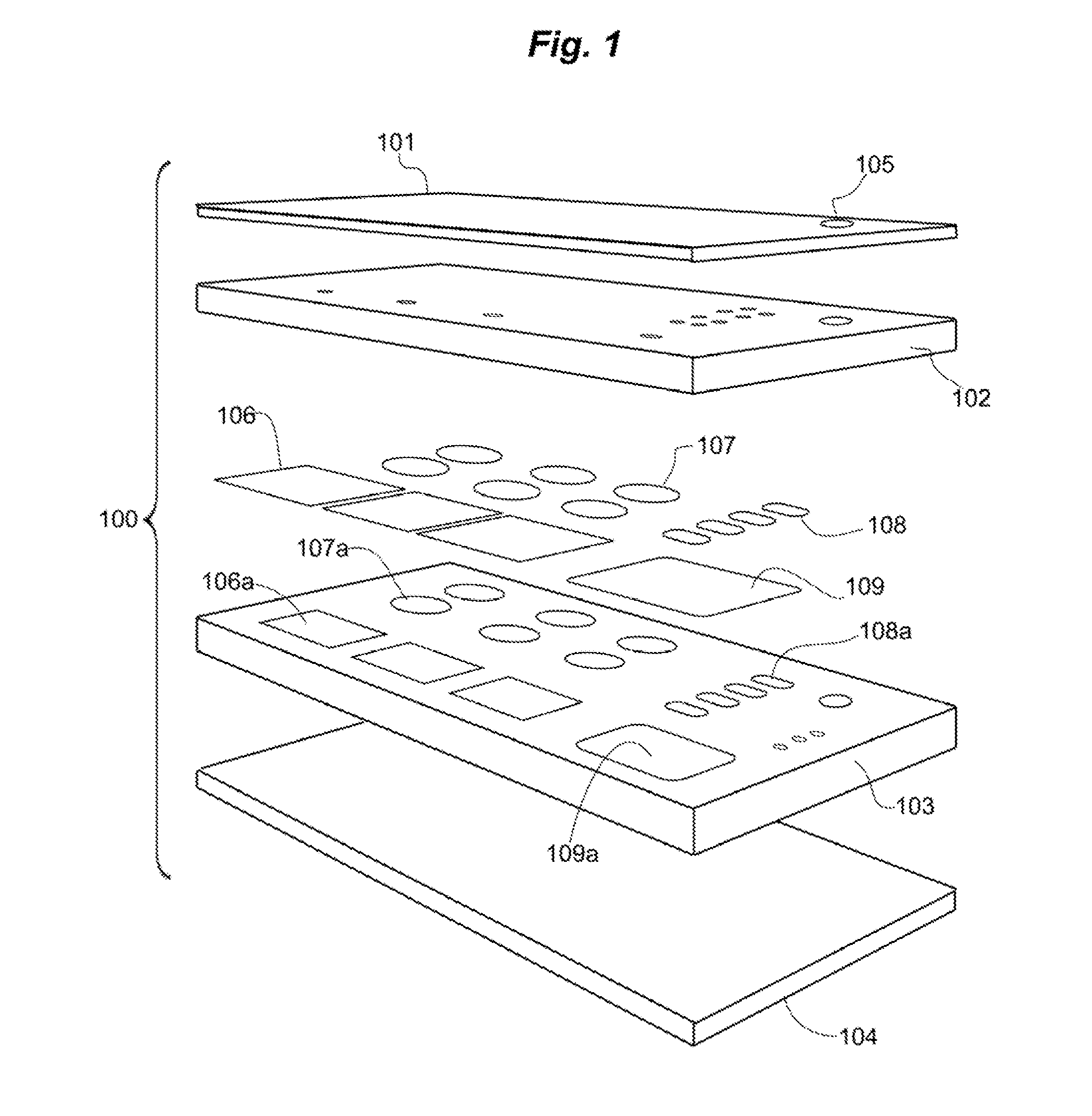
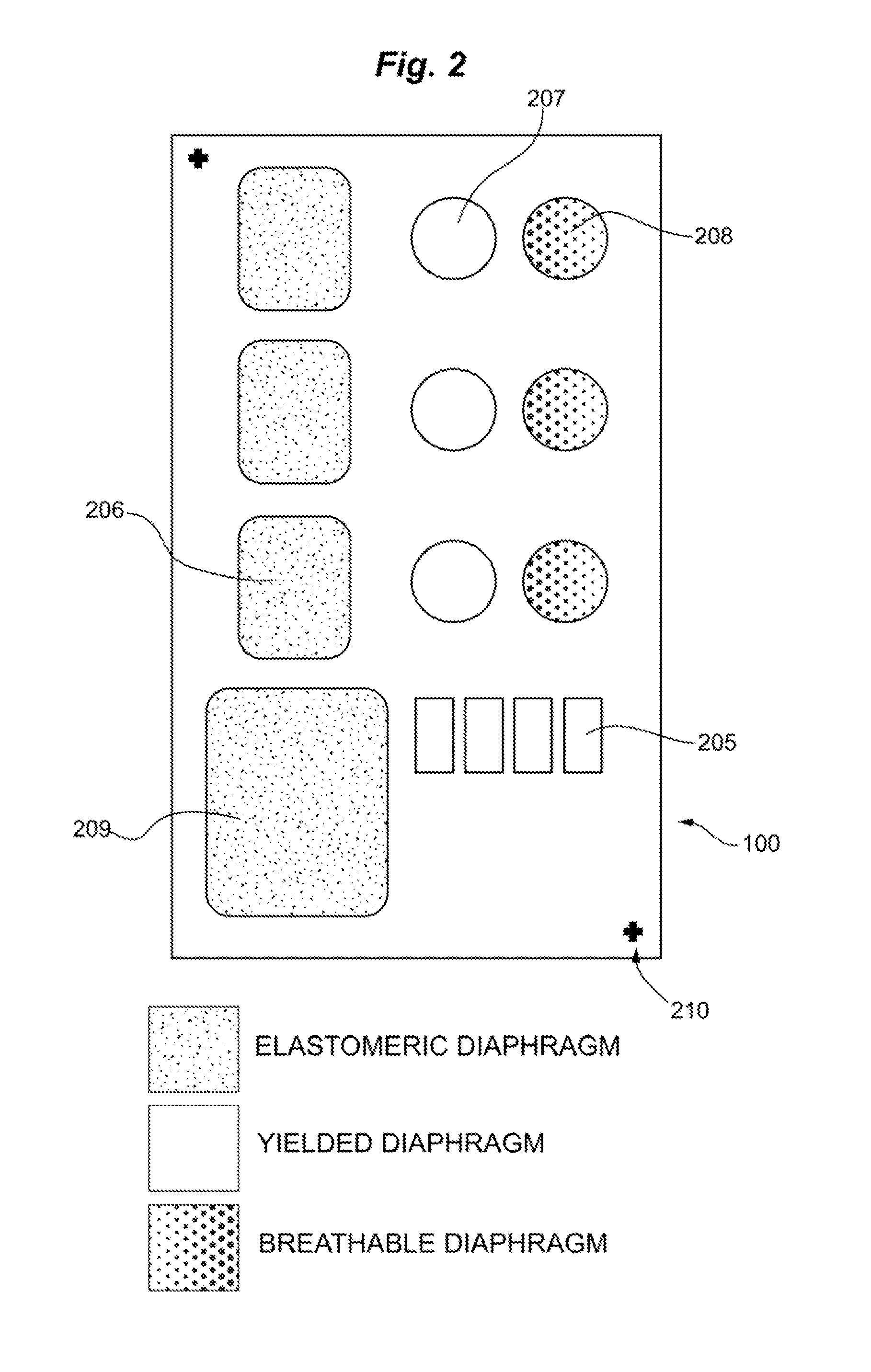
[0058]The foregoing and other objectives, features, and advantages of the invention will be more readily understood upon consideration of the following detailed description of the invention, taken in conjunction with the accompanying drawings, in which preferred embodiments of the invention are illustrated by way of example. It is to be expressly understood, however, that the drawings are for illustration and description only and are not intended as a definition of the limits of the invention. The various features of novelty that characterize the invention are pointed out with particularity in the claims annexed to and forming part of this disclosure. The invention does not necessarily reside in any one of these features taken alone, but rather in the particular combination of all of its structures for the functions specified.

[0059]Certain terms throughout the following description are used to refer to particular features, steps or components, and are used as terms of description an...


PUM

PropertyMeasurementUnit
Lengthaaaaaaaaaa
Lengthaaaaaaaaaa
Forceaaaaaaaaaa

Abstract

Fluidic cartridges, and manufacture thereof, having a plurality of circuit element subtypes containing pneumatically operated diaphragm members, where the diaphragm materials are selected for yield point, chemical resistance, breathability and other properties individually according to the fluidic element subtype are provided. A process of in-situ edge-bonded decoupage for forming diaphragm members inside a cartridge, and fluidic circuits having diaphragm members as active and passive circuit elements, including pumps, valves, vents, waste receptacles, reagent reservoirs, and cuvettes with optical windows, where the material composition of each individual diaphragm member may be selected from an assortment of materials during manufacture are also provided.

Description

BACKGROUND[0001]1. Technical Field[0002]The present invention generally relates to fluidic devices, such as microfluidic devices, and methods for manufacture and use of the same.[0003]2. Description of the Related Art[0004]Fluidic microcircuits are known in the art, and include mechanical systems such as piston driven devices, electrohydraulic systems such as electrokinetic pump and valve devices, and pneumohydraulic systems. Of these, those systems with pneumatic actuators and control surfaces have proven most practical in controlling microscale fluid flows.[0005]One class of fluidic devices having a pneumatic interface is manufactured by Micronics, Inc. (Redmond, Wash.). Control of fluid flow in microfluidic channels is achieved with a MICROFLOW® system pneumatic controller, which operates millimeter-sized valves in a plastic cartridge according to programmable valve logic. Miniature diaphragms separate the pneumatic side and the hydraulic side of the cartridges; i.e., the valve d...

Claims


Application Information

Patent Timeline
IPC IPC(8): B01L3/00B29C65/16B29C43/02F16K99/00
CPCB01L3/50273Y10T156/1026F16K99/0059B29C65/16B29C43/021F16K2099/0084F16K2099/0086B01L2400/0487B01L2300/0887B01L2200/12B01L2400/0638B29K2101/00B29L2009/00B29L2031/7496F16K99/0015B01L3/502707B01L3/502738B01L2200/0689B01L2300/0816B01L2300/0874B01L2300/123B01L2400/0481B01L2400/0655B81B2201/052B81C1/00119F04B43/043F16K2099/0078F16K2099/008
Inventor KOLB, ANDREWSPRAGUE, ISAACKAY, JUSTIN L.BRAGD, MATTHEW SCOTTSTONE, MARTHA
Owner PERKINELMER HEALTH SCIENCES INC
Why Eureka
Try Eureka