Internal combustion engine

a combustion engine and combustion chamber technology, applied in the direction of electrical control, corrosion prevention fuel injection, instruments, etc., can solve the problem of difficulty in accurately predicting the course of achieve the effect of reducing the nozzle tip temperature reduction rate, increasing the heat receiving amount of the nozzle, and less likely to be reduced the nozzle tip temperatur

Active Publication Date: 2015-12-10
TOYOTA JIDOSHA KK
View PDF9 Cites 9 Cited by
  • Summary
  • Abstract
  • Description
  • Claims
  • Application Information

AI Technical Summary

Benefits of technology

[0012]The nozzle heat receiving amount can be increased when the racing implementation control, the idle extension control, or the measure for raising the idle rotation speed is performed. When the nozzle heat receiving amount is increased, the heat dissipation rate of the nozzle following the increase in the nozzle heat receiving amount becomes gradual and the nozzle tip temperature reduction rate is reduced. In other words, the nozzle tip temperature becomes less likely to be reduced. As a result, the dew point arrival time can be increased and the dew condensation in the nozzle tip portion can be inhibited.
[0013]The control unit may improve a piston temperature reduction rate during the control for the improvement of the temperature reduction rate of the part positioned around the nozzle. When a piston is selected as the part positioned around the nozzle and the piston temperature reduction rate is improved, the timing when the piston reaches the dew point temperature precedes the timing when the nozzle reaches the dew point temperature. Accordingly, the dew condensation in the nozzle tip portion is avoided.
[0014]The control unit may introduce a coolant in a radiator into an engine main body and may improve a cylinder bore wall temperature reduction rate during the control for the improvement of the temperature reduction rate of the part positioned around the nozzle. When a bore wall is selected as the part positioned around the nozzle and the bore wall temperature reduction rate is improved, the timing when the bore wall reaches the dew point temperature precedes the timing when the nozzle reaches the dew point temperature. Accordingly, the dew condensation in the nozzle tip portion is avoided.
[0015]The control unit may reduce, that is, slow down the nozzle tip temperature reduction rate by supplying hot water in a heat storage tank to a cylinder head on which the injector is mounted during the control for the improvement of the temperature reduction rate of the part positioned around the nozzle. Heat dissipation from the nozzle becomes less likely to occur when the heat amount of the cylinder head on which the injector is mounted rises. As a result, the nozzle tip temperature reduction rate becomes gradual. Then, the dew point arrival time of the nozzle tip portion is increased and the dew condensation in the nozzle tip portion becomes less likely to occur.
[0016]According to the internal combustion engine disclosed in the specification, the occurrence of the dew condensation in the nozzle tip portion can be accurately determined.

Problems solved by technology

Accordingly, even if the nozzle tip temperature at a certain point in time is acquired, it is difficult to accurately predict the course of the nozzle tip temperature reduction following that point in time and reaching the occurrence of the dew condensation.

Method used


Image

  • Internal combustion engine
  • Internal combustion engine
  • Internal combustion engine

Examples


first embodiment

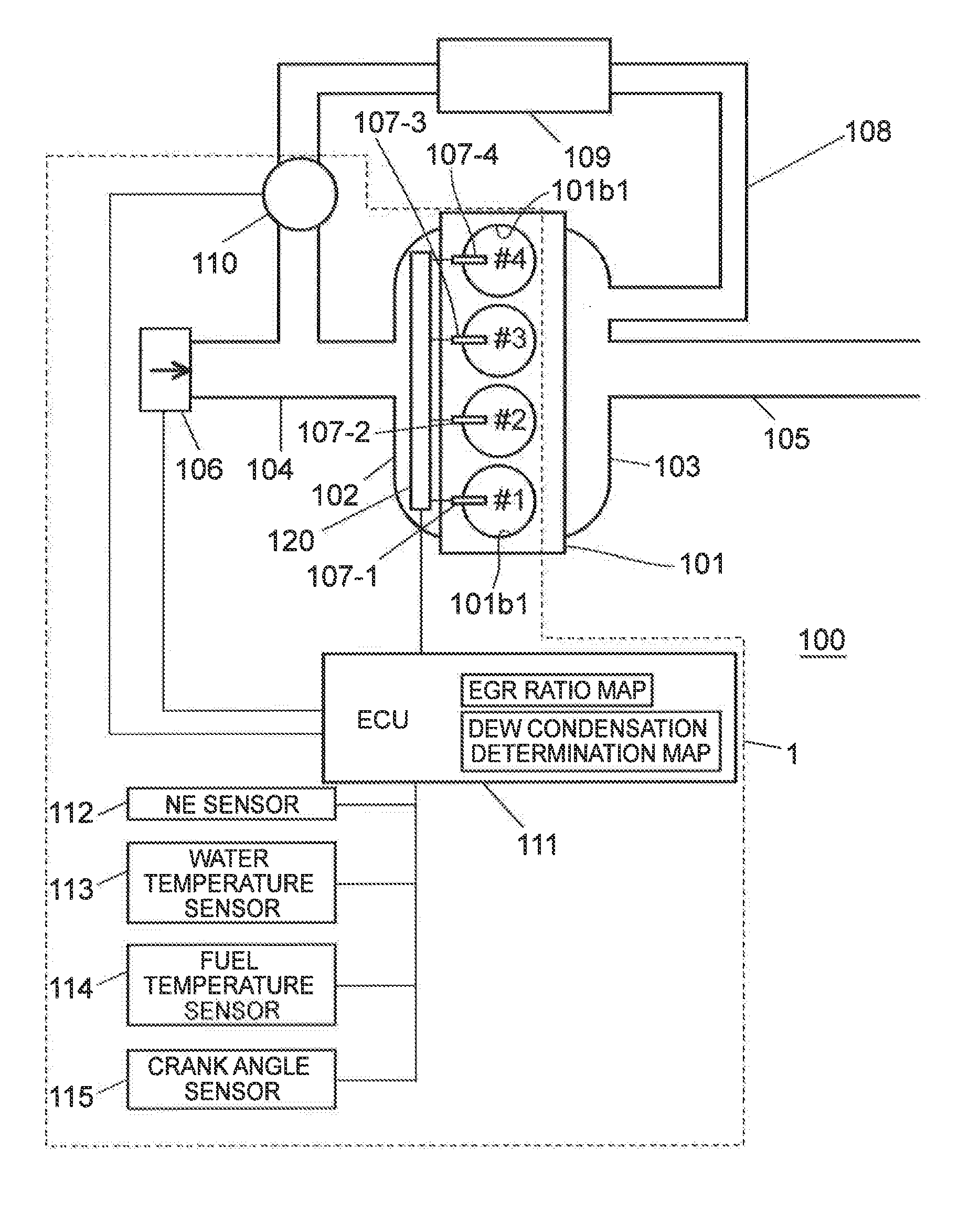
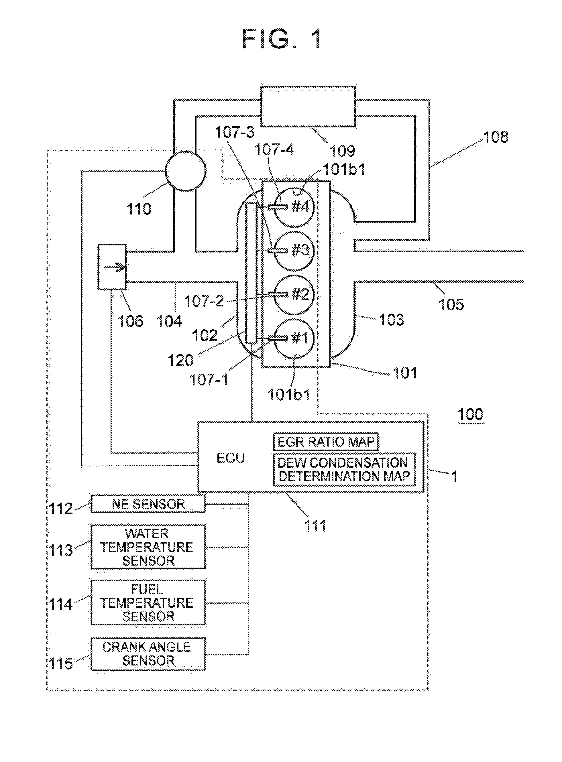
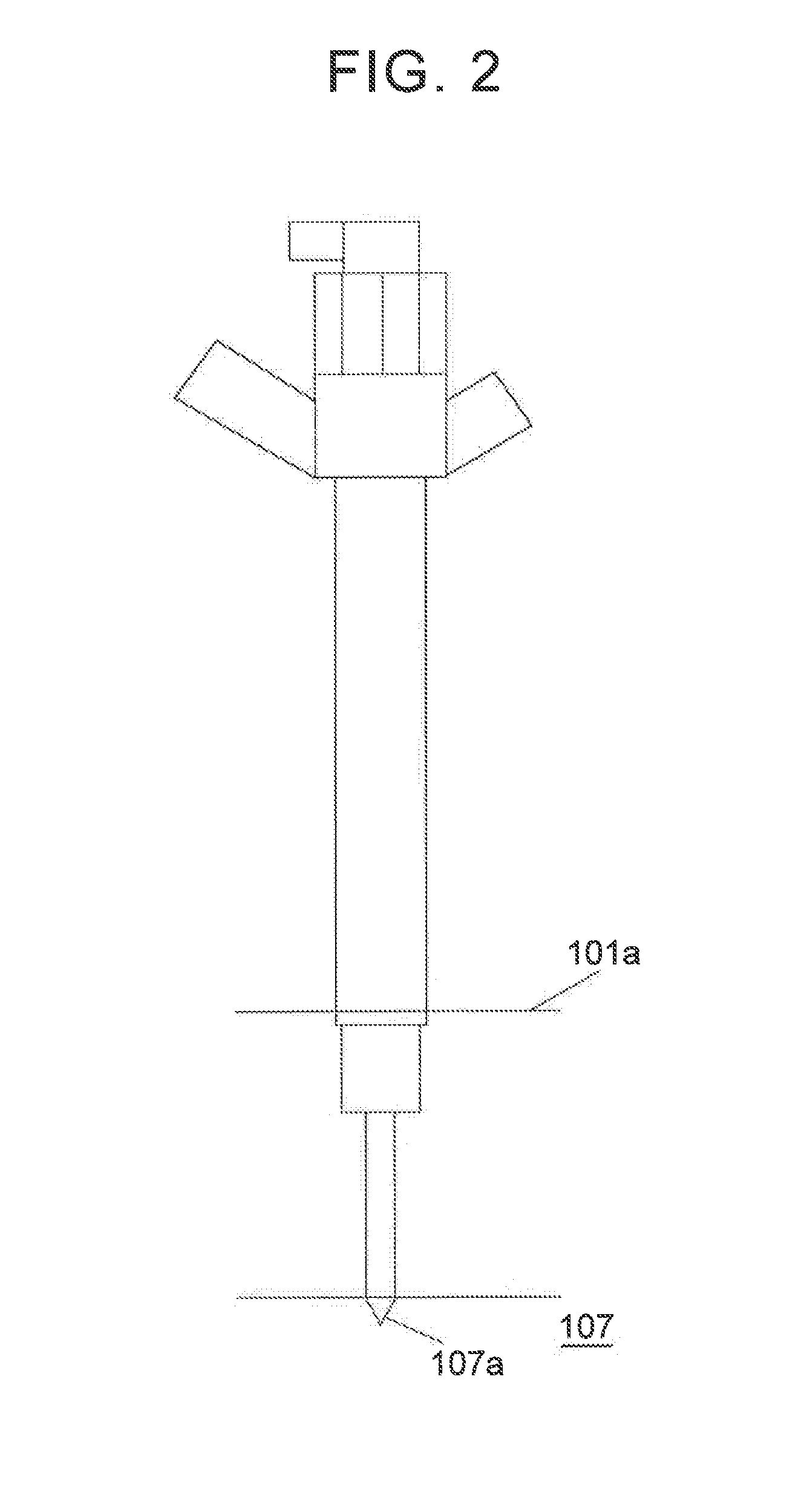
[0039]FIG. 1 is an explanatory drawing illustrating a schematic configuration of an internal combustion engine 100 according to a first embodiment. A fuel injection device 1 is incorporated into the internal combustion engine 100. The internal combustion engine 100 is an internal combustion engine that performs in-cylinder injection, more specifically, a diesel internal combustion engine. The internal combustion engine 100 is a four-cylinder internal combustion engine. The internal combustion engine 100 is provided with an engine main body 101 that is provided with a cylinder head 101a and a cylinder block 101b, and is provided with #1 to #4 cylinders in the engine main body 101. The fuel injection device 1 is incorporated into the internal combustion engine 100. The fuel injection device 1 is provided with #1 to #4 injectors 107-1 to 107-4 corresponding to the #1 to #4 cylinders. Specifically, the #1 injector 107-1 is mounted on the #1 cylinder, the #2 injector 107-2 is mounted on ...

second embodiment

[0065]Hereinafter, a second embodiment will be described with reference to FIGS. 8 and 9. FIG. 8 is a flow diagram illustrating an example of the control of the internal combustion engine 100 according to the second embodiment, specifically, idle extension control. FIGS. 9A and 9B are graphs illustrating the change in the nozzle tip temperature that is caused by idle extension.

[0066]The difference between the second embodiment and the first embodiment lies in details of the nozzle corrosion prevention control (control for nozzle heat dissipation rate reduction) performed by the ECU 111. In the second embodiment, the idle extension control is performed instead of the racing implementation control of the first embodiment. In other words, the details of Steps S1 to S8 in the flow diagram illustrated in FIG. 4 are identical to those of the first embodiment. The basic configuration of the internal combustion engine 100 is identical to that of the first embodiment, and thus detailed descr...

third embodiment

[0076]Hereinafter, a third embodiment will be described with reference to FIGS. 10 to 13. FIG. 10 is a block diagram illustrating a main part of the internal combustion engine 100 according to the third embodiment. FIG. 11 is a flow diagram illustrating an example of the control of the internal combustion engine 100 according to the third embodiment. FIG. 12 is an explanatory drawing schematically illustrating the manner of piston cooling according to the third embodiment. FIGS. 13A and 13B are graphs illustrating the effect of the piston cooling.

[0077]Referring to FIGS. 10 and 12, the internal combustion engine 100 according to the third embodiment is provided with an electric oil pump 121, which is electrically connected to the ECU 111, as a main part thereof. As illustrated in FIG. 12, the electric oil pump supplies oil to oil jets 122 that cool pistons 101c which are accommodated in a cylinder block 101b. The oil jets 122 are disposed in the respective cylinders, inject the oil ...


PUM

PropertyMeasurementUnit
temperatureaaaaaaaaaa
arrival timeaaaaaaaaaa
heat dissipation rateaaaaaaaaaa

Abstract

An internal combustion engine includes a control unit determining the occurrence or non-occurrence of dew condensation in a tip portion of a nozzle based on a nozzle heat receiving amount of an injector and a nozzle tip temperature of the injector at a point in time when ignition is turned OFF and performing nozzle corrosion prevention control when the dew condensation is determined to occur in the nozzle tip portion. The control unit calculates a nozzle tip temperature reduction rate based on the nozzle heat receiving amount, calculates a dew point arrival time based on the reduction rate, and determines the occurrence or non-occurrence of the dew condensation in the nozzle tip portion based on the dew point arrival time.

Description

TECHNICAL FIELD[0001]The present invention relates to an internal combustion engine.BACKGROUND ART[0002]It has been known that an injection hole disposed in a nozzle tip portion of an injector injecting a fuel into a cylinder of an internal combustion engine may be subjected to corrosion because acid-containing moisture causes dew condensation in and condensed water adheres to the nozzle tip portion. Whether the dew condensation in the nozzle tip portion occurs or not is affected by the relationship between the temperature of the nozzle tip and the dew point of the in-cylinder atmosphere. In view of this point, PTL 1 proposes corrosion reduction by means of nozzle tip temperature estimation and EGR amount adjustment based on the estimated nozzle tip temperature.CITATION LISTPatent Literature[0003]PTL 1: Japanese Patent Application Publication No. 2010-255462SUMMARY OF THE INVENTION[0004]The nozzle tip temperature is involved with the adherence of condensed water to the nozzle tip po...

Claims


Application Information

Patent Timeline
Patent Type & Authority Applications(United States)
IPC IPC(8): F02D35/02G01N25/66F01P7/14F02M53/04F02D35/00
CPCF02D35/025F02M53/04G01N25/66F01P7/14F02D35/0007F02D41/042F02M2200/05
Inventor IKEMOTO, MASATONAKAGAWA, MASAYOSHIMATSUMOTO, TAKASHIYAMASHITA, YOSHIO
Owner TOYOTA JIDOSHA KK
Why Eureka
Try Eureka