

System for testing valves
a valve and valve body technology, applied in the field of systems and methods for testing valves, can solve problems such as unrepresentative tests, and achieve the effects of reducing valve overstress, reducing valve overstress, and speeding up the speed of the process
- Summary
- Abstract
- Description
- Claims
- Application Information
AI Technical Summary
Benefits of technology
Problems solved by technology
Method used
Image

Examples
Embodiment Construction
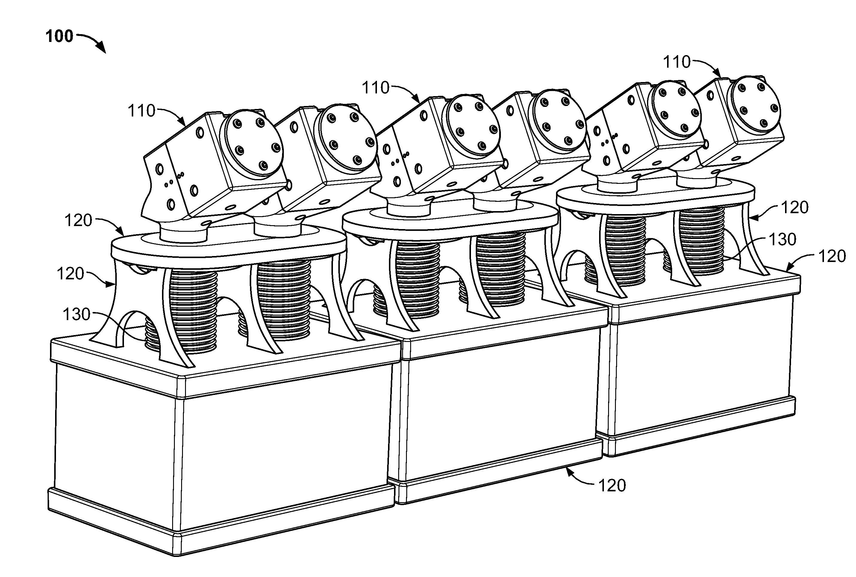
[0035]This document provides systems and methods for testing various kinds of valves. For example, this document provides systems and methods for accelerated life testing of prosthetic heart valves.
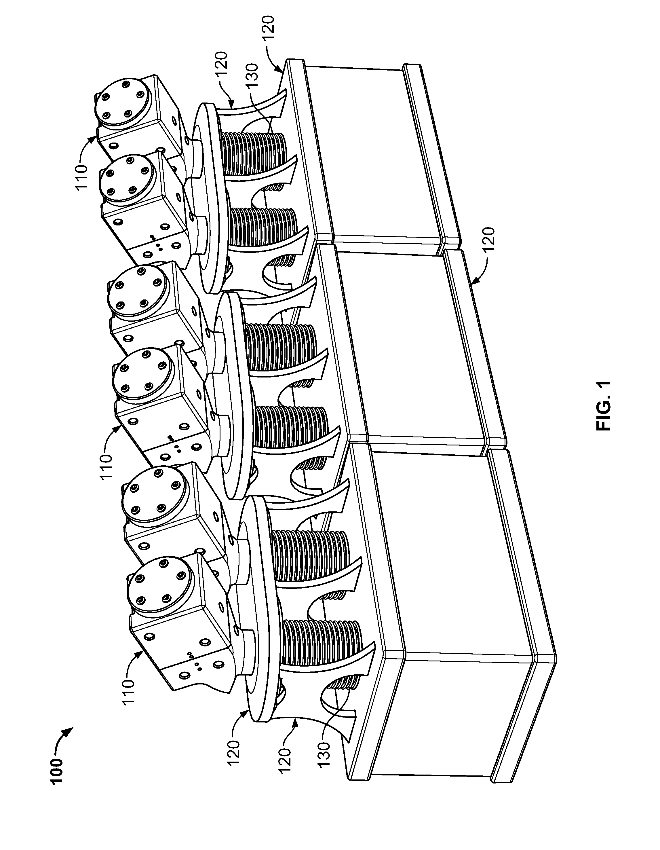
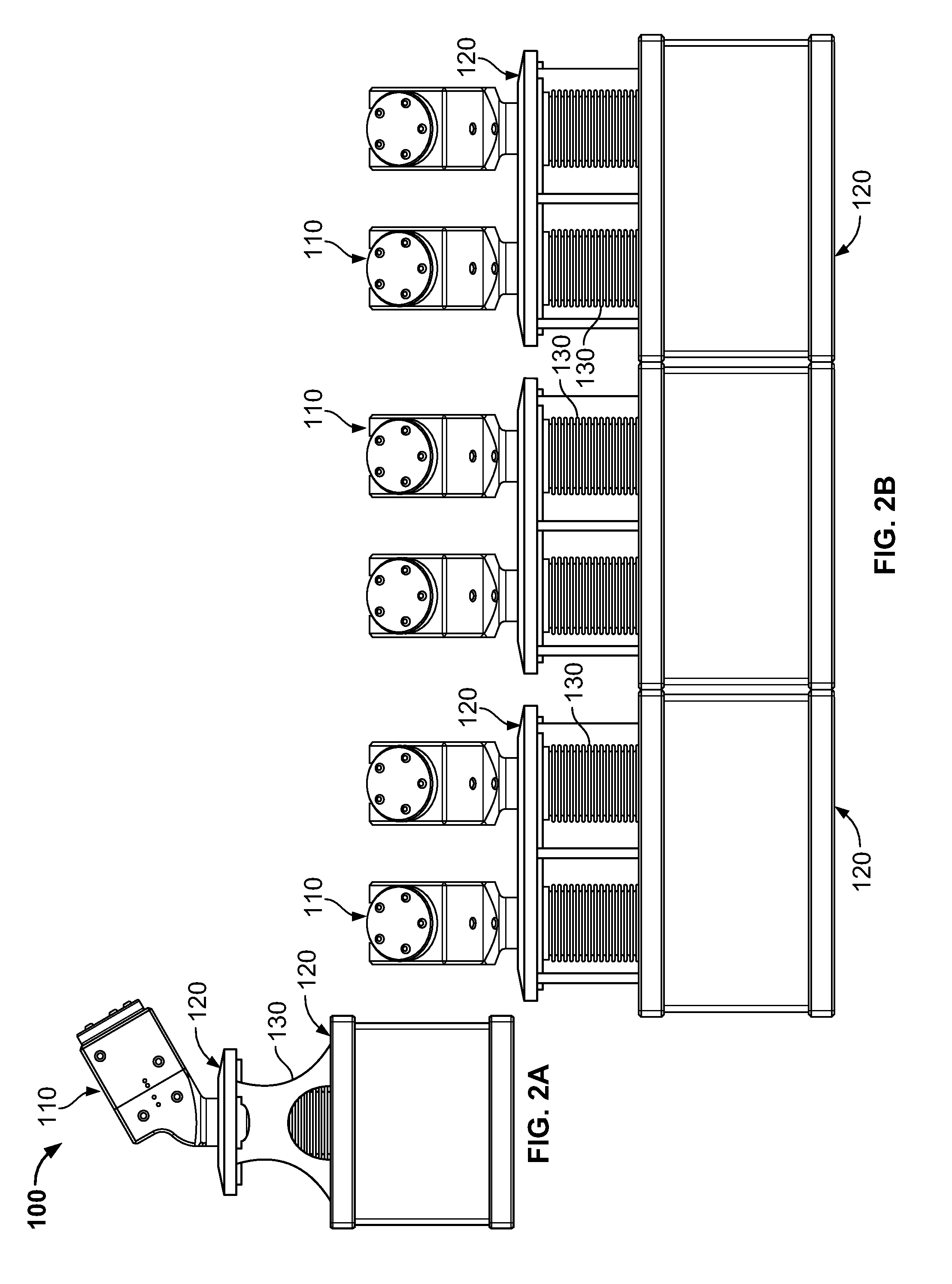
[0036]Referring to FIGS. 1, 2A, and 2B an example multi-station accelerated life testing (ALT) system 100 includes multiple chambers 110, a framework 120, and multiple bellows 130. The chambers 110 and the bellows 130 are mounted to and are supported by the framework 120. Each individual chamber 110 is in fluid communication with a corresponding individual bellows 130 located below the individual chamber 110, or a flexible membrane diaphragm 121 can be optionally used between the chamber 110 and bellows 130 in some embodiments. The bellows 130 can be axially extended or compressed, as will be described further below.
[0037]The internal spaces of the chamber 110 and the bellows 130 can receive a liquid (e.g., saline, water, and the like). Accordingly, an axial extension or compression of th...
PUM
 Abstract
Description
Claims
Application Information