Methods and systems for improving hybrid vehicle cooling

a hybrid vehicle and cooling technology, applied in the field of hybrid vehicle cooling systems and methods, can solve the problems of not being able to convert all of the kinetic energy of the vehicle, reducing the vehicle's ability to recover and conserve energy, and reducing the ability to recover. the electric machine, reducing the possibility of degrading the electric machine, and saving energy

Active Publication Date: 2015-12-17
FORD GLOBAL TECH LLC
View PDF19 Cites 15 Cited by
  • Summary
  • Abstract
  • Description
  • Claims
  • Application Information

AI Technical Summary

Benefits of technology

[0002]A hybrid vehicle may recharge an electrical energy storage device during breaking, while maintaining vehicle speed down a hill in cruise control, and during pedal off deceleration (e.g., accelerator and brakes not applied) via regenerative braking. In particular, the electrical energy storage device may be recharged by converting the vehicle's kinetic energy into electrical energy by operating an electric machine in a generator mode. However, it may not be possible to convert all of the vehicle's kinetic energy into electrical energy for several reasons. For example, if the electric machine is producing a large amount of current, the electric machine's temperature may increase to a level where the electric machine's current is reduced to lower the possibility of degrading the electric machine. As a result, a portion of the vehicle's kinetic energy may be converted into heat energy by vehicle brakes for the vehicle to follow a desired deceleration rate. The heat energy produced by the vehicle brakes may be lost to the atmosphere, thereby reducing the vehicle's ability to recover and conserve energy.
[0004]By selectively operating an electric pump, it may be possible to provide the technical result of improved driveline cooling during regenerative braking. Specifically, an electric pump that supplies transmission clutches transmission fluid when a driveline is not being rotated by an engine or electric machine may also be operated when the electric machine is rotating to provide an increased flow rate of transmission fluid to increase electric machine cooling. The electric pump may be operated at the same time as a mechanical pump so that both pumps provide transmission fluid to cool the electric machine during times of increased heat generation by the electric machine. For example, the electric pump may supply transmission fluid to the electric machine when the electric machine is converting the vehicle's kinetic energy into electrical energy.
[0005]The present description may provide several advantages. In particular, the approach may improve driveline component cooling. Additionally, the approach may conserve energy when driveline cooling requirements are low and improve driveline cooling when additional driveline cooling may be desired. Further still, the approach may provide additional driveline cooling without additional expense.

Problems solved by technology

However, it may not be possible to convert all of the vehicle's kinetic energy into electrical energy for several reasons.
The heat energy produced by the vehicle brakes may be lost to the atmosphere, thereby reducing the vehicle's ability to recover and conserve energy.

Method used


Image

  • Methods and systems for improving hybrid vehicle cooling
  • Methods and systems for improving hybrid vehicle cooling
  • Methods and systems for improving hybrid vehicle cooling

Examples


Embodiment Construction

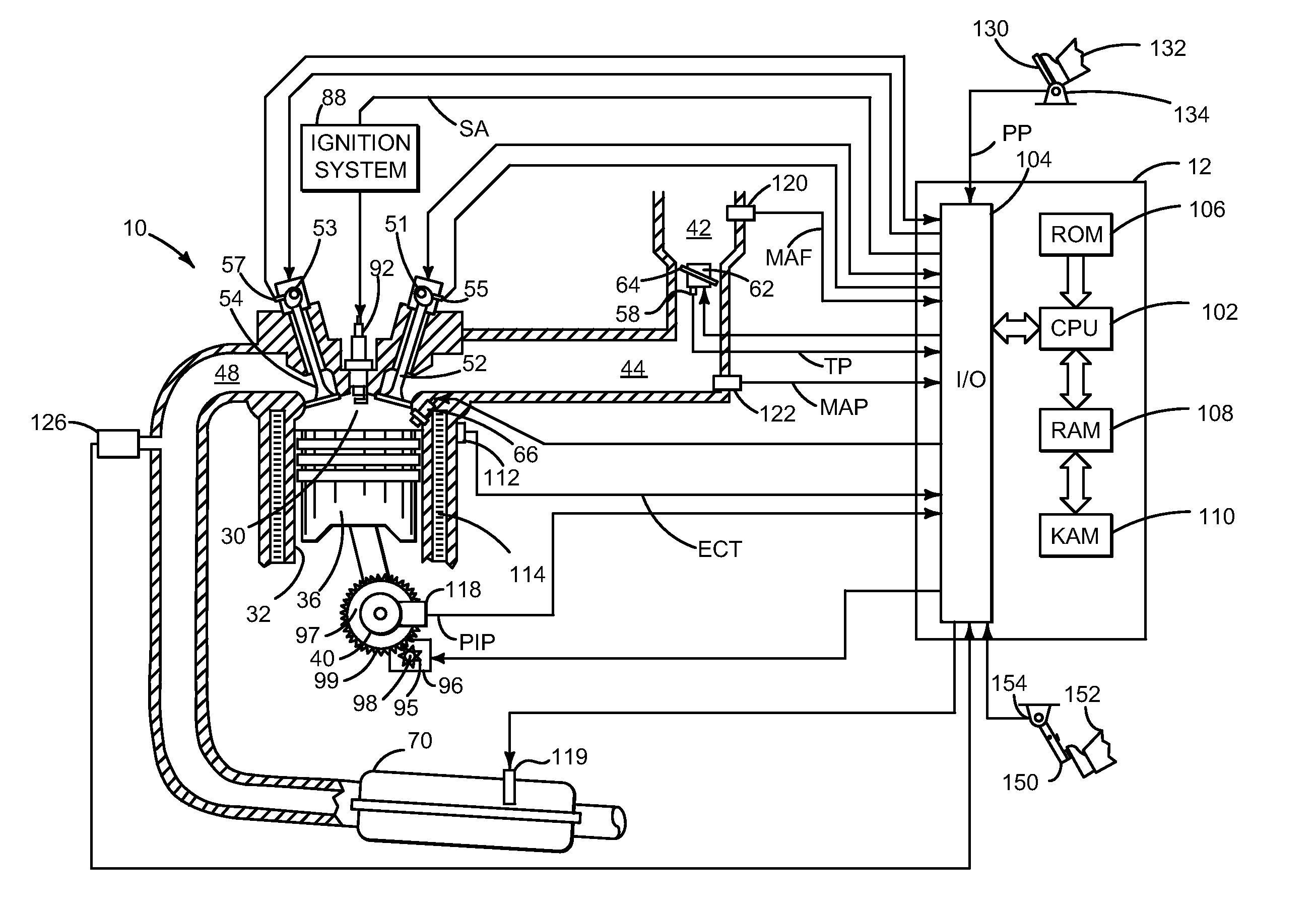
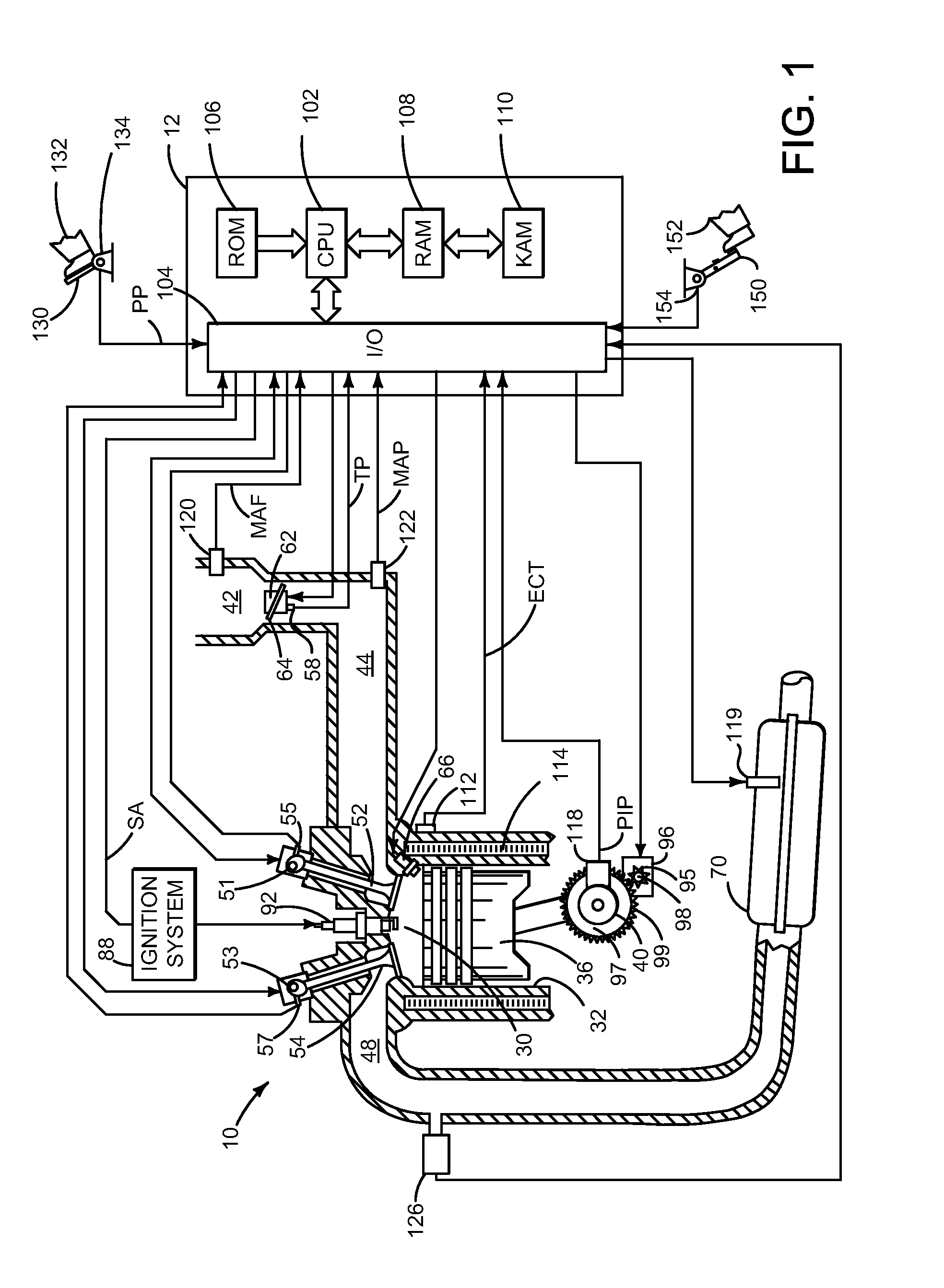
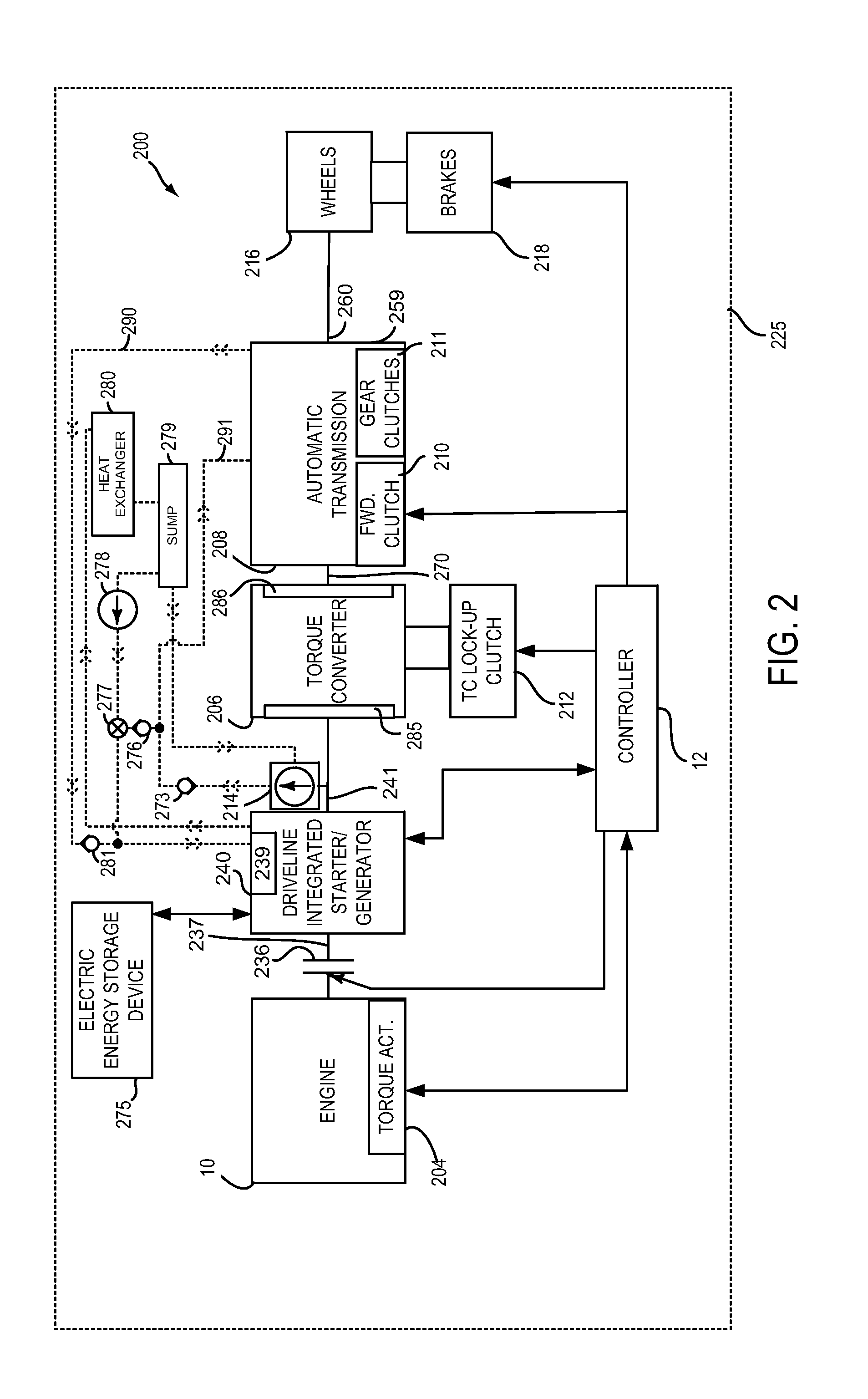
[0013]The present description is related to controlling driveline cooling of a hybrid vehicle. The driveline may include an engine as is shown in FIG. 1. The engine may be mechanically coupled to other vehicle components to form a driveline as is shown in FIG. 2. The driveline may include an electric machine for propelling the vehicle and an electric pump for supplying transmission fluid to transmission clutches when the engine and electric machine are not rotating. The electric pump may also be operated when the engine and / or electric machine are rotating to provide additional cooling to the electric machine as is shown in FIG. 3. The electric pump may be operated according to the method of FIG. 4 to provide the operating sequence of FIG. 3.

[0014]Referring to FIG. 1, internal combustion engine 10, comprising a plurality of cylinders, one cylinder of which is shown in FIG. 1, is controlled by electronic engine controller 12. Engine 10 includes combustion chamber 30 and cylinder wall...


PUM


Abstract

Systems and methods for improving hybrid vehicle cooling are presented. In one example, an electric pump may supply transmission fluid to a transmission and a driveline integrated starter / generator to cool, operate, and lubricate driveline components. The electric pump may be selectively operated to conserve energy and to supply driveline cooling when driveline cooling may be desirable.

Description

FIELD[0001]The present description relates to a system and methods for improving cooling of a hybrid vehicle. The methods may be particularly useful for hybrid vehicles that include regenerative braking.BACKGROUND AND SUMMARY[0002]A hybrid vehicle may recharge an electrical energy storage device during breaking, while maintaining vehicle speed down a hill in cruise control, and during pedal off deceleration (e.g., accelerator and brakes not applied) via regenerative braking. In particular, the electrical energy storage device may be recharged by converting the vehicle's kinetic energy into electrical energy by operating an electric machine in a generator mode. However, it may not be possible to convert all of the vehicle's kinetic energy into electrical energy for several reasons. For example, if the electric machine is producing a large amount of current, the electric machine's temperature may increase to a level where the electric machine's current is reduced to lower the possibil...

Claims


Application Information

Patent Timeline
Patent Type & Authority Applications(United States)
IPC IPC(8): B60W20/00F16H57/04F16H61/00
CPCB60W20/1062F16H61/0031Y10S903/902F16H57/0476F16H2061/0037F16H57/0413B60K6/48B60W10/02B60W10/06B60W10/08B60W10/30B60W20/00B60W30/1843B60W2510/08B60W2510/087B60Y2200/92B60Y2306/05Y02T10/62B60W2710/088B60W20/14B60W20/15F16H57/0417F16H57/0446
Inventor NEFCY, BERNARD D.KRASKA, MARVIN PAULORTMANN, WALTER JOSEPH
Owner FORD GLOBAL TECH LLC
Why Eureka
Try Eureka