Magnetic Resonance Imaging

a magnetic resonance imaging and magnetic resonance technology, applied in the field of magnetic resonance imaging and magnetic resonance devices, can solve the problems of restricting the existing homogeneity of the main magnetic field, further source of inhomogeneity, and recording of inferior magnetic resonance image data, so as to and improve the quality of the calculated b0 map

Inactive Publication Date: 2015-12-17
SIEMENS AG
View PDF7 Cites 7 Cited by
  • Summary
  • Abstract
  • Description
  • Claims
  • Application Information

AI Technical Summary

Benefits of technology

[0023]One embodiment provides that the acquisition of the first magnetic resonance image data takes place from a first recording region and the acquisition of the second magnetic resonance image data takes place from a second recording region. The second recording region is a partial region of the first recording region. Thus, the first recording region may be larger than the second recording region. The first magnetic resonance image data, which serves as the basis for generating the shim settings for the second magnetic resonance image data, therefore may represent a larger region of the object under investigation than the second magnetic resonance image data. This is advantageous, since distortions of the main magnetic field may also have effects at remote sites. Thus, an inhomogeneity of susceptibilities in a shoulder region of the object under investigation may have an effect on the main magnetic field and thus on an image quality during a heart examination. The enlargement of the recording region of the first magnetic resonance image data relative to the second magnetic resonance image data takes account of this fact since susceptibilities that lie outside the second magnetic resonance image data may thus also be taken into account in the calculation of the shim settings for the second magnetic resonance image data. In this way, the quality of the calculated B0 map may be improved, and the image quality of the second magnetic resonance image data may be increased. Alternatively, or in addition, a model of the object under investigation may also be generated based on the first magnetic resonance image data, and for the calculation of the B0 map, an anatomy of the object under investigation based on the model may be extrapolated beyond the limits of the first magnetic resonance image data. The contours of the object under investigation may be of particular interest herein. Thus, the generation of the B0 map may be based on a still larger field of view.
[0024]Another embodiment provides that the acquisition of the first magnetic resonance image data takes place during a movement of a patient table of the magnetic resonance device. A recording technique of this type is known as “move-during-scan” recording or “continuous-table-motion” recording. In this way, the first magnetic resonance image data may be recorded in a particularly time-saving manner. By the movement of the patient table, a very large part of the object under investigation may also be recorded in the shortest possible time. This may contribute to the first magnetic resonance image data having a significantly larger recording region than the second magnetic resonance image data.
[0025]Another embodiment provides that before the acquisition of the second magnetic resonance image data, first scan data is acquired by at least one further sensor different from the magnetic resonance

Problems solved by technology

Even small deviations in the homogeneity may lead to large deviations in a frequency distribution of the nuclear spin so that qualitatively inferior magnetic resonance image data is recorded.
Once a magnetic resonance device has been installed at a designated location, fields present in the surroundings may restrict the existing homogeneity of the main magnetic field (e.g., around an isocenter of the magnetic resonance device).
However, a further source of inhomogeneity is the object under investigation itself.
If, for example, a person under investigation

Method used


Image

  • Magnetic Resonance Imaging
  • Magnetic Resonance Imaging
  • Magnetic Resonance Imaging

Examples


first embodiment

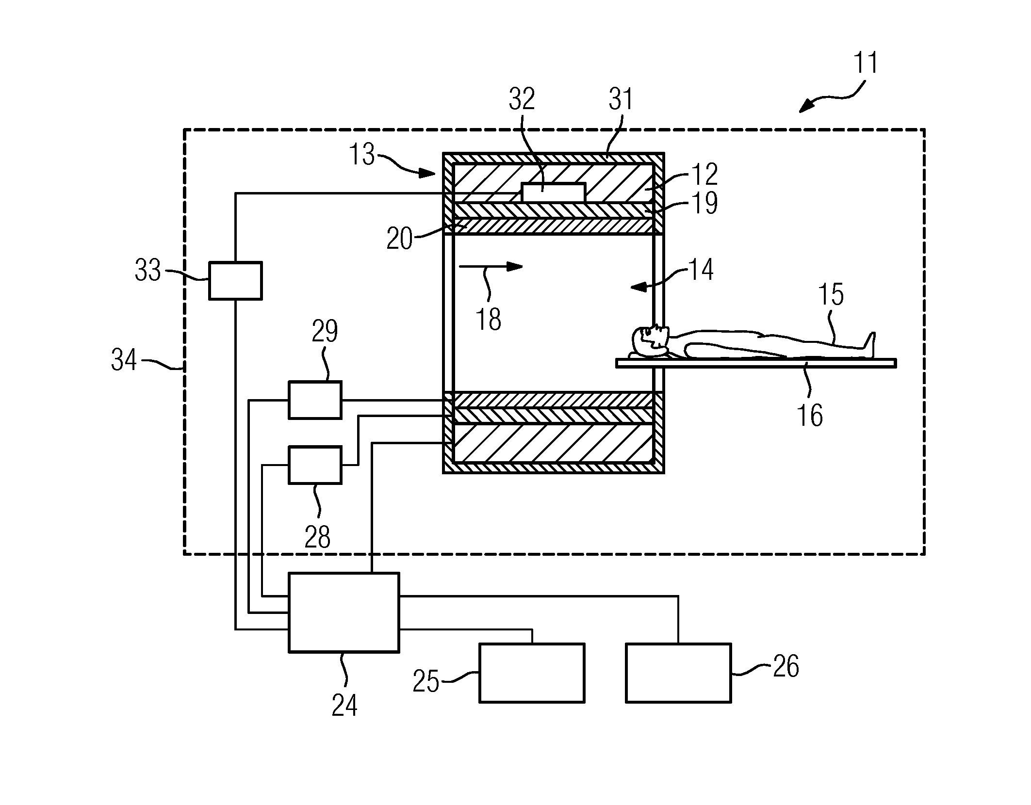
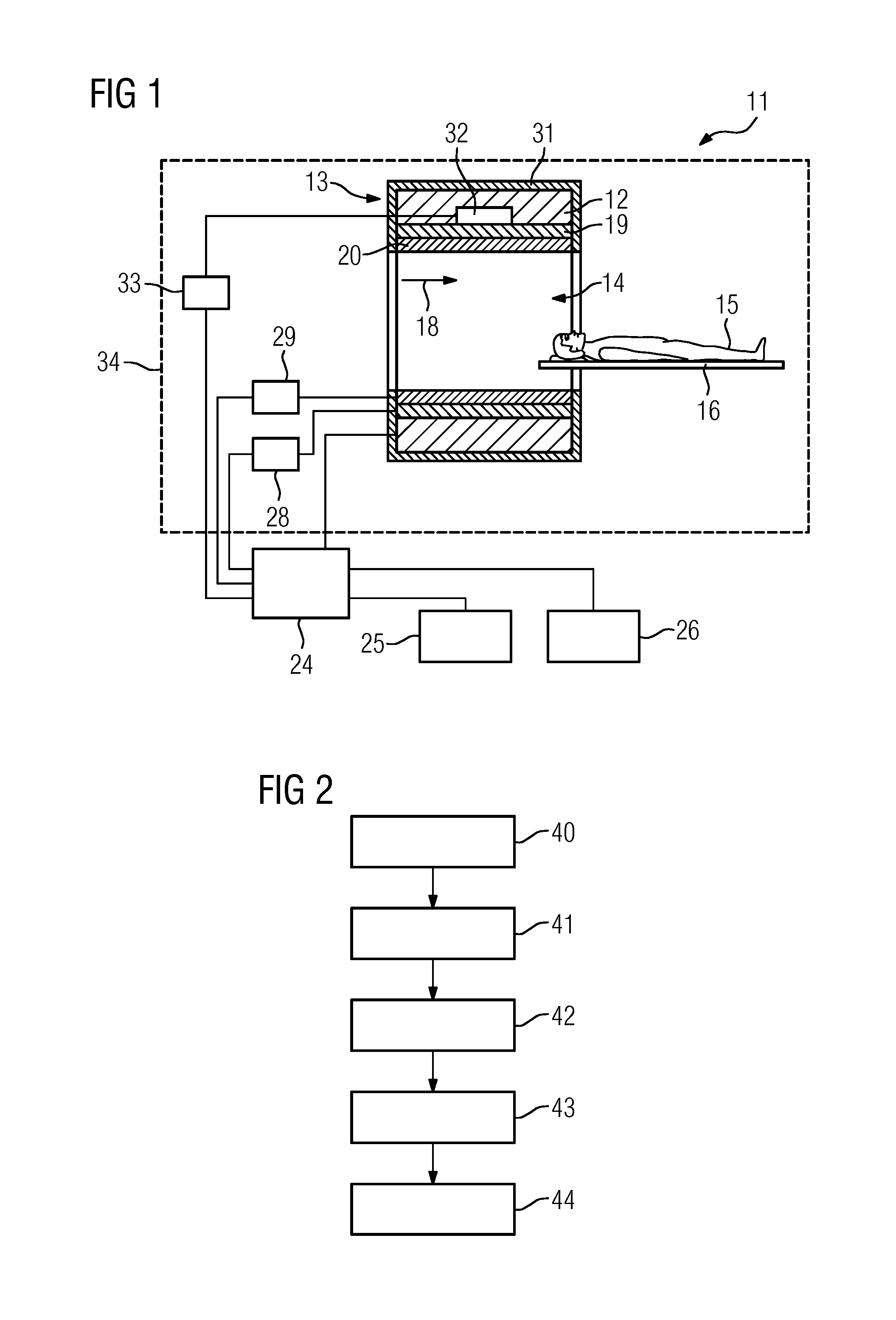
[0043]FIG. 2 shows a flow diagram of a method for magnetic resonance imaging of an object under investigation 15 using a magnetic resonance device 11.

[0044]In a first method act 40, first magnetic resonance image data of the object under investigation 15 is acquired by an image data acquisition unit 34 of the magnetic resonance device 11. This may take place, for example, during recording of a three-dimensional scout view at the start of an investigation of the object under investigation 15. In act 41, the first magnetic resonance image data is segmented by a segmenting unit (not shown) of the computer unit 24 into at least two material classes. In act 42, a calculating unit (not shown) of the computer unit 24 calculates a B0 map based on the segmented first magnetic resonance image data and based on susceptibility values of the at least two material classes. In a further act 43, shim settings are calculated by the shim control unit 33 based on the calculated B0 map. In method act 4...

second embodiment

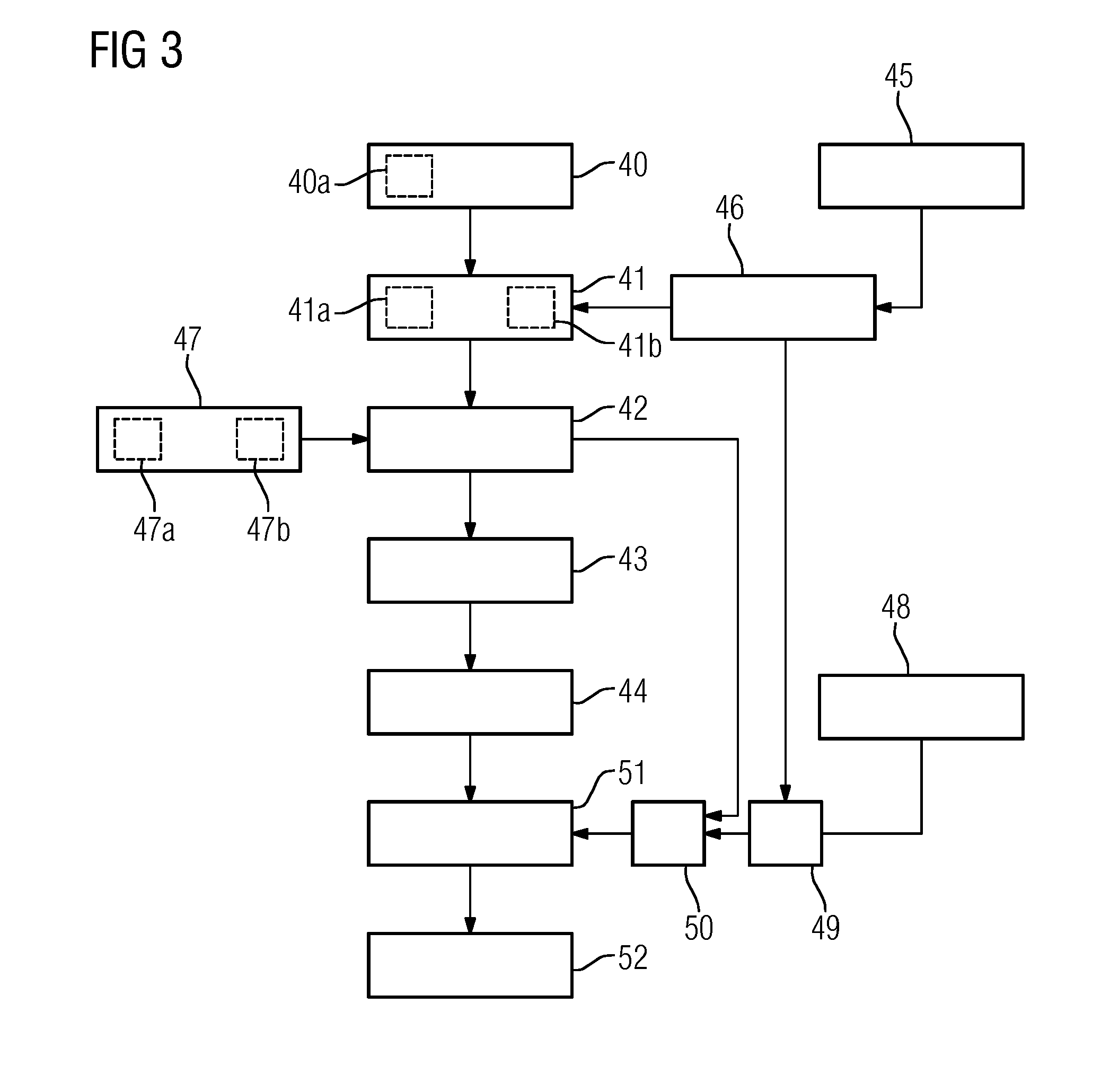
[0045]FIG. 3 shows a flow diagram of a method.

[0046]The following description is essentially restricted to the differences from the exemplary embodiment in FIG. 2, where, with regard to method acts that remain the same, reference is made to the description of the exemplary embodiment in FIG. 2. Method acts that are substantially the same are essentially identified with the same reference signs.

[0047]The second embodiment of the method shown in FIG. 3 essentially includes the method acts 40, 41, 42, 43, 44 of the first embodiment of the method, as shown in FIG. 2. The second embodiment of the method shown in FIG. 3 also includes further method acts and sub-acts. Also conceivable is an alternative method sequence to that of FIG. 3 that has only part of the additional method acts and / or sub-acts09 represented in FIG. 2. An alternative method sequence to that of FIG. 3 may also have additional method acts and / or sub-acts.

[0048]The acquisition of the first magnetic resonance image data i...

third embodiment

[0052]FIG. 4 shows a flow diagram of a method according to one or more of the present embodiments.

[0053]The following description is essentially restricted to the differences from the exemplary embodiment in FIG. 2, where, with regard to method acts that remain the same, reference is made to the description of the exemplary embodiment in FIG. 2. Method acts that are substantially the same are essentially identified with the same reference signs.

[0054]The third embodiment of the method shown in FIG. 4 essentially includes the method acts 40, 41, 42, 43, 44 of the first embodiment of the method, as shown in FIG. 2. The method sequence shown in FIG. 4 includes the further method act 47 of the second embodiment of the method in FIG. 3. In addition, the third embodiment of the method shown in FIG. 4 also includes further method acts and sub-acts. An alternative method sequence to that of FIG. 4, which has only part of the additional method acts and / or sub-acts represented in FIG. 2, may ...


PUM


Abstract

In order to enable efficient calculation of shim settings for a magnetic resonance imaging system, a method for magnetic resonance imaging of an object under investigation using a magnetic resonance device is provided. The method includes acquiring first magnetic resonance image data of the object under investigation using the magnetic resonance device. The method also includes segmenting the first magnetic resonance image data into at least two material classes, calculating a B0 map based on the segmented first magnetic resonance image data and based on susceptibility values of the at least two material classes, and calculating shim settings based on the calculated B0 map. The method also includes acquiring second magnetic resonance image data of the object under investigation using the magnetic resonance device. The acquisition of the second magnetic resonance image data is undertaken using the calculated shim settings.

Description

[0001]This application claims the benefit of DE 10 2014 211 354.7, filed on Jun. 13, 2014, which is hereby incorporated by reference in its entirety.BACKGROUND[0002]The present embodiments relate to a method for magnetic resonance imaging and a magnetic resonance device.[0003]In a magnetic resonance device (e.g., a “magnetic resonance tomography system”), the body of the subject to be examined (e.g., of a patient) is typically exposed to a relatively strong magnetic field of, for example, 1.5 or 3 or 7 Tesla, with the aid of a main magnet. In addition, gradient pulses are applied with the aid of a gradient coil unit. Using a high frequency antenna unit, using suitable antenna devices, high frequency pulses (e.g., excitation pulses) are then transmitted, which has the effect that the nuclear spins of particular atoms excited into resonance by these high frequency pulses are tilted through a defined flip angle relative to the magnetic field lines of the main magnetic field. On relaxat...

Claims


Application Information

Patent Timeline
IPC IPC(8): G01R33/565G01R33/3875G01R33/48
CPCG01R33/56563G01R33/3875G01R33/4828G01R33/243G01R33/56536
Inventor BIBER, STEPHANNIEDERLOHNER, DANIELSCHMIDT, ANDREASVESTER, MARKUS
Owner SIEMENS AG
Why Eureka
Try Eureka