Method for design and manufacturing of optics for holographic sight

a technology of optics and manufacturing methods, applied in the direction of optical elements, mechanical apparatus, instruments, etc., can solve the problems of low light throughput, irregular see-through sight optics, and the inability to implement laser diodes in sights, etc., to achieve the effect of optimizing image quality

Active Publication Date: 2015-12-17
LUMINIT
View PDF1 Cites 20 Cited by
  • Summary
  • Abstract
  • Description
  • Claims
  • Application Information

AI Technical Summary

Benefits of technology

[0010]Another aspect of the disclosure provides a method of design and recording holographic optical elements for substrate-guided holographic sight using an intermediate hologram and a ray-tracing technique that includes optimization of image quality using a damped-least square optimization procedure for the merit function minimization.

Problems solved by technology

The disadvantage of regular see-through sight optics is in low light throughput due to the unavoidable losses of semitransparent optics for both see-through and reticle image.
Implementing laser diodes in sights is questionable as accumulated exposure to bright laser light / scatter in the visible spectrum range can bring to damage of the shooter's eye.
Speckled reticle image is also an issue.
The deficiency of existent holographic sights is in implementing laser diodes to avoid dispersion and in rather complicated multi-element optics needed to compensate aberrations [5-A. M. Tai, E. Sieczka, ‘Lightweight Holographic Sight’, U.S. Pat. No. 6,490,060 B1 (2002), Assignee EOTech Inc.].
This sight optics, with the reticle image recorded in the hologram, requires individual time consuming alignment of each element, and applied laser diode creates the coherent reticle image with significant speckle that is negatively affecting the image perception.
Such approach indeed allowed for a see-through imagery with simultaneous view of the outside world, however the image quality was rather poor for a broad-band light source, mostly because of the color dispersion created by a single hologram for a broad-band source; for a laser-based (narrow-band) source, an unwanted shift in virtual image position was observed with a drift in laser diode wavelength due to, e.g., external temperature changes.
While providing a see-through capability, such approach suffers from stray light generated by unwanted diffraction into undesired diffractive orders that substantially decreases the image quality and contrast.
While creating a see-through imagery, fabrication of such elements in mass quantities can be prohibitively expensive, and providing a needed long eye-relief (˜100 mm) is not possible.
While indeed showing a good image quality for up to 4.0 mm diameter Eye Box size, the demonstrated Eye Box size is not large enough to provide an adequate see-through sight.

Method used


Image

  • Method for design and manufacturing of optics for holographic sight
  • Method for design and manufacturing of optics for holographic sight
  • Method for design and manufacturing of optics for holographic sight

Examples


Embodiment Construction

[0021]In the following, unless otherwise stated, the term recorded or recording refers to the fabrication of a holographic element.

[0022]Although the present invention is susceptible of embodiment in various forms, there is shown in the drawings and will hereinafter be described presently preferred embodiments with the understanding that the present disclosure is to be considered as an exemplification of the invention and is not intended to limit the invention to specific embodiments illustrated.

[0023]It is to be further understood that the title of this section of the specification, namely, “Detailed Description of the Preferred Embodiments” relates to a rule of the United States Patent and Trademark Office, and is not intended to, does not imply, nor should be inferred to, limit the subject matter disclosed herein or the scope of the invention.

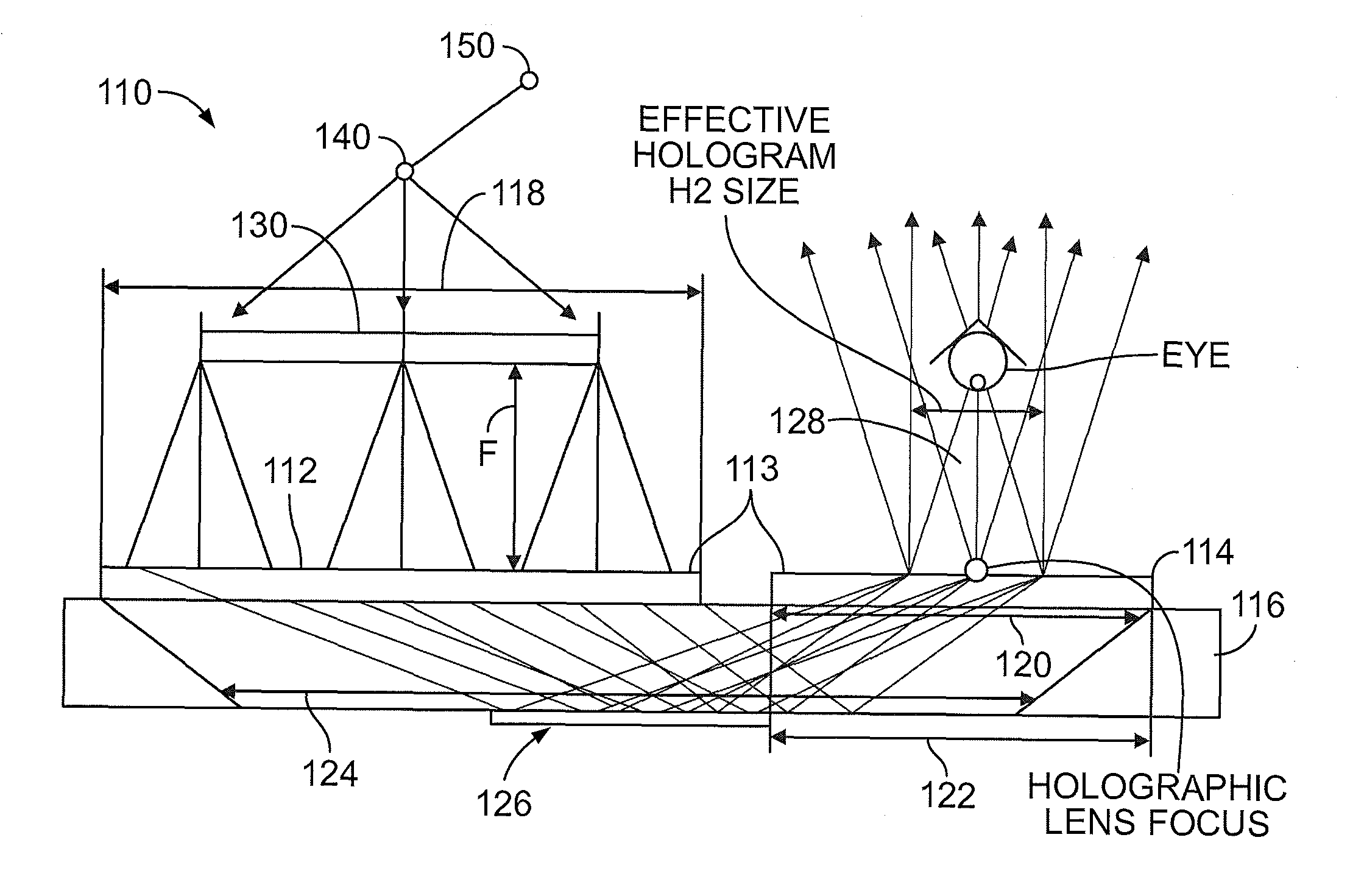
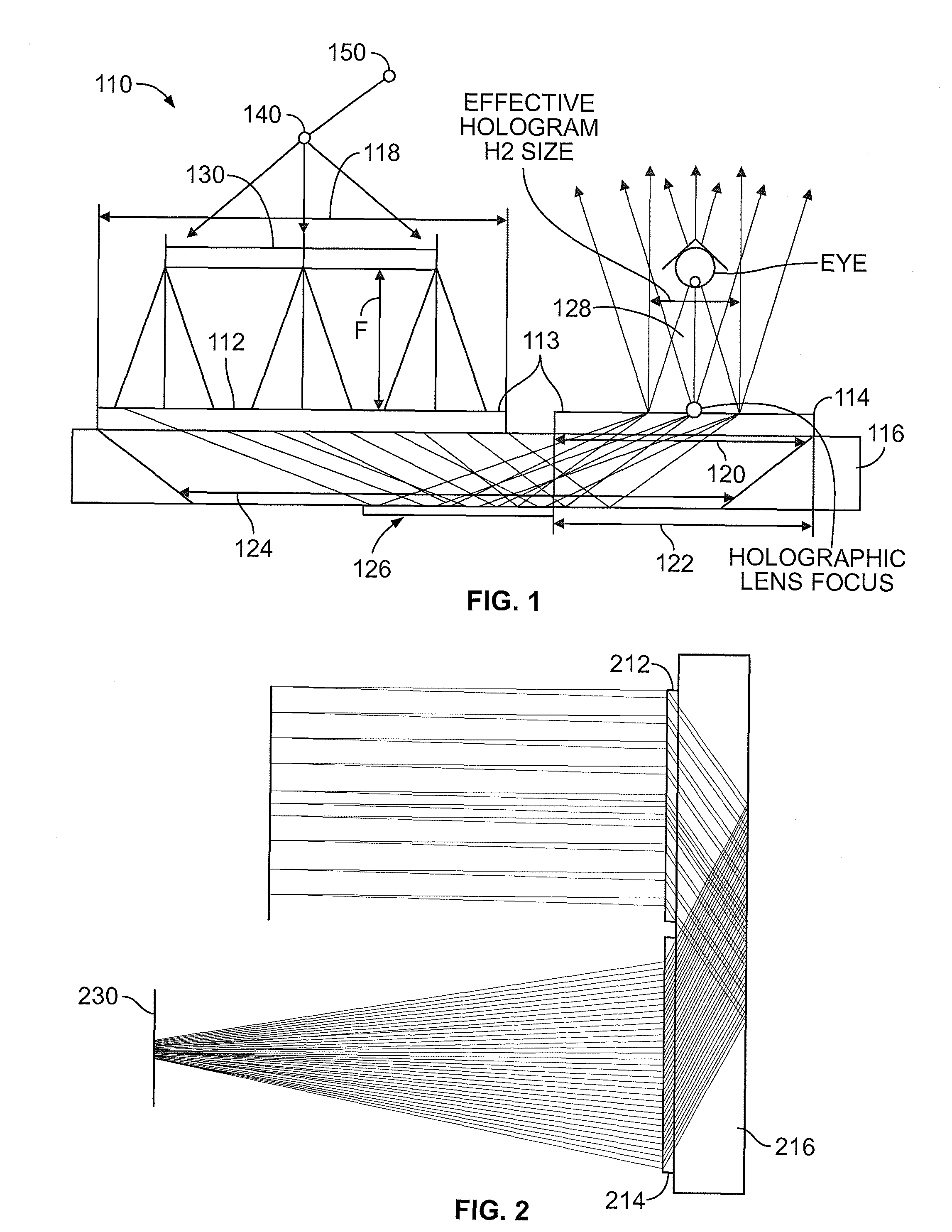
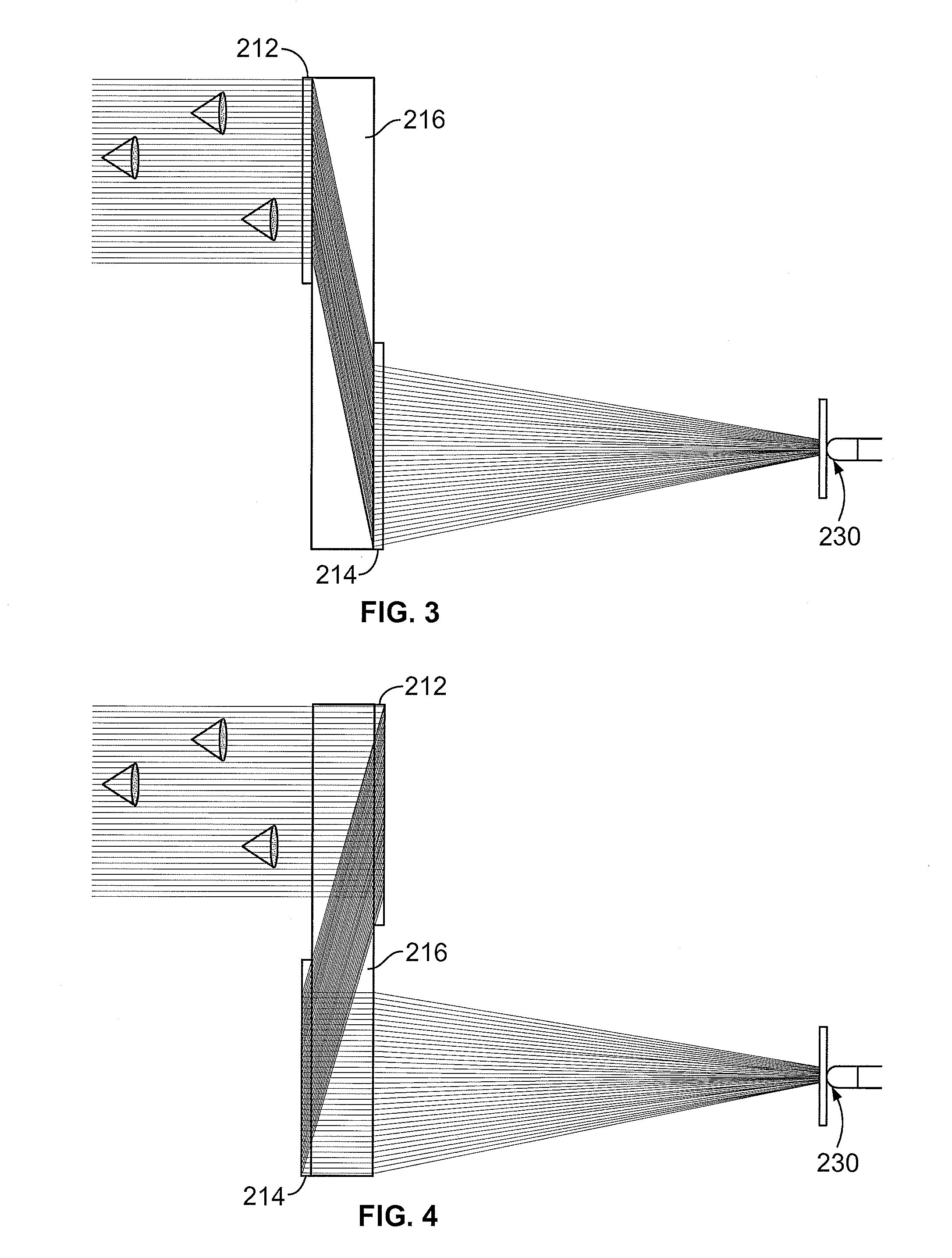
[0024]The method of the subject invention comprises a design for the optics of a see-through holographic weapon sight, with the optical par...


PUM


Abstract

A method for design and fabrication of holographic optical elements for a compact holographic sight is proposed. The method includes use of ray-trace software to design holographic elements having optical power using an intermediate hologram with parameters obtained through minimization of the merit function defining image quality.

Description

BACKGROUND OF THE INVENTION[0001]See-through optical sights for simulation, training, and close combat (distances less than ˜1000 m) based on collimated optics have been in use for years. [1—Elementary optics and applications to fire control instruments: May, 1921 By United States. Army. Ordnance Dept, page 84, 2—R. P. Grauslys, A. R. Harding, ‘Weapon Aiming Device’, U.S. Pat. No. 7,530,192 B2 (2009)]. The advantage of collimated optics based sights is in the reticle image appearing in the same plane or close to the target plane. This makes the targeting more precise and comfortable. Usually, a see-through monocular optical sight consists of a reticle illuminated with some small light source, reflective and / or refractive optics to create a magnified virtual image of the reticle for a viewer's eye. The simplest type of reticle is a “red dot”—just an LED or laser diode as a reticle. The disadvantage of regular see-through sight optics is in low light throughput due to the unavoidable ...

Claims


Application Information

Patent Timeline
Patent Type & Authority Applications(United States)
IPC IPC(8): G02B5/32G03H1/04F41G1/00G02B23/26G02B23/24G03H1/02F21V8/00
CPCG02B5/32G03H1/0272G03H1/0443F41G1/00G02B6/0025G02B23/26G02B23/2407G03H1/0486F41G1/30G02B27/0103G02B27/0189G03H2001/0439G03H2001/2226G03H2001/261
Inventor VOLOSCHENKO, DMITRYARIK, ENGIN B.DIMOV, FEDORYU, KEVINYIN, KHIN (LILLIAN) SWERAKULJIC, NEVEN
Owner LUMINIT
Why Eureka
Try Eureka