Method and Arrangement for Operating a Phased Antenna Array

Active Publication Date: 2015-12-24
RF SHAMAANIT
View PDF34 Cites 12 Cited by
  • Summary
  • Abstract
  • Description
  • Claims
  • Application Information

AI Technical Summary

Benefits of technology

[0020]Chaining the antenna units, circulating a data collection frame, and summing the properly delayed contribution from each antenna with pre-existing data in the data collection frame enables increasing the number of antennas (or antenna groups) in the chain with little or no additional increase in the bandwidth required for collecting the data. The data rate in the connection through the chain of antenna units, through which the collection of data is accomplished, can be completely independent of the number of antenna units in the chain; adding antenna units to the chain may increase the overall delay before the collected data arrives at the central unit, but this has seldom any negative consequence

Problems solved by technology

It is easy to see that a large number of antennas in the array of FIG. 1 means an extremely large amount of cabling.
The larger the system grows, the more complicated become tasks like cable ditch digging and pr

Method used


Image

  • Method and Arrangement for Operating a Phased Antenna Array
  • Method and Arrangement for Operating a Phased Antenna Array
  • Method and Arrangement for Operating a Phased Antenna Array

Examples


Embodiment Construction

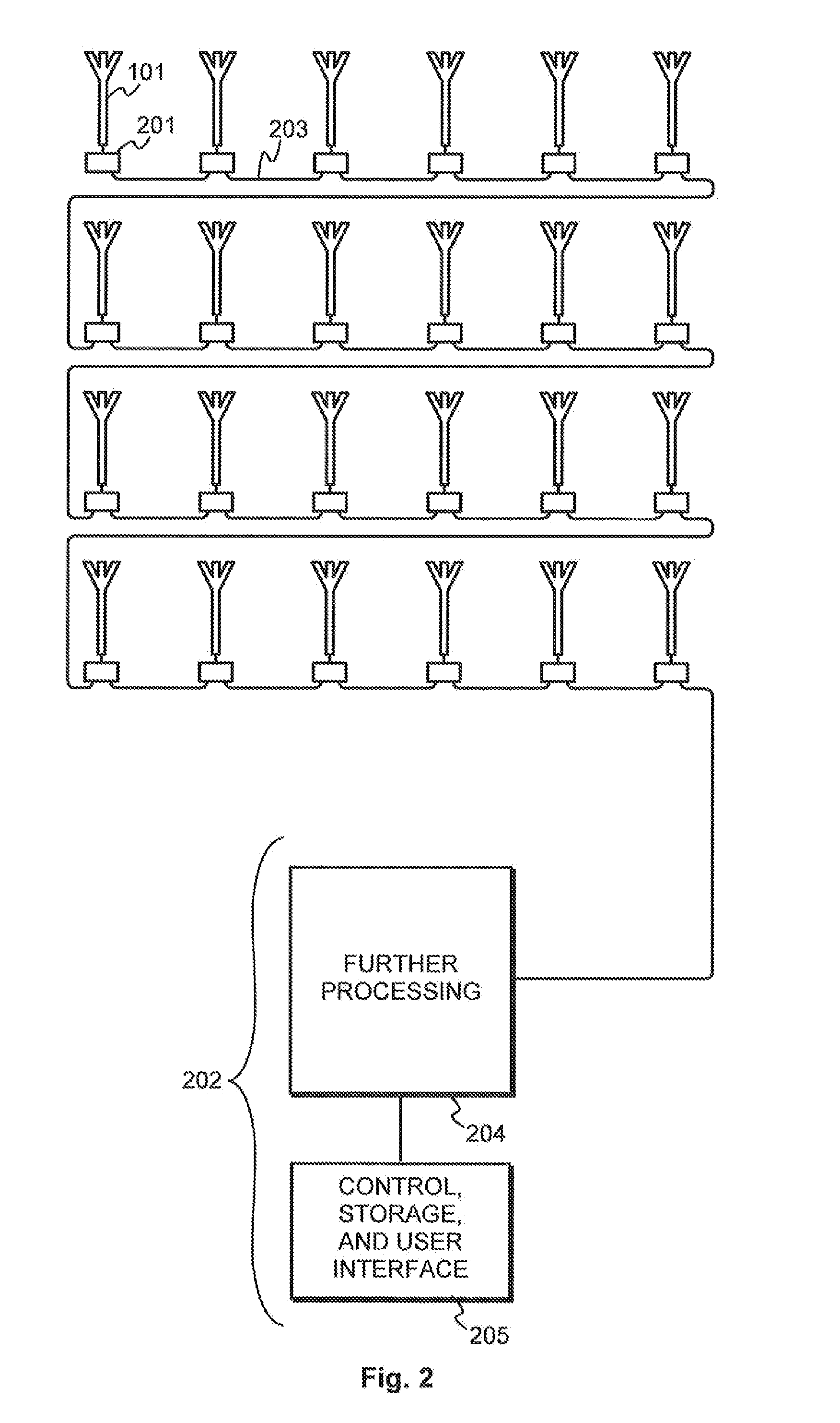
[0042]FIG. 2 illustrates an antenna arrangement, which comprises a multitude of antennas for use as an antenna array. As such the antennas may be similar to any previously known antennas, for which reason the same reference number 101 is used for an exemplary antenna as in the description of prior art. In order to be used as an antenna array they are typically distributed over a relatively large area. The signal that is received by the antennas is called a measurement signal.

[0043]The antenna arrangement comprises a multitude of functional blocks which are designated as antenna units in this description. In this description we use the designation “antenna unit” to refer to a functional block, which does not (necessarily) include the antenna proper but which includes electronic components arranged to process signals received through the antenna(s) and to communicate with other antenna units. Antenna unit 201 is shown as an example. Each antenna unit is coupled to receive a measuremen...


PUM


Abstract

An antenna unit is used in an antenna array. It comprises a measurement signal receiver for receiving and digitizing a measurement signal from an antenna. A time delay unit delays the digitized measurement signal. A data collection receiver receives a data collection frame, and a data collection transmitter is configured to sum the delayed digitized measurement signal with pre-existing data in the received data collection frame and to transmit the so constructed updated data collection frame further.

Description

TECHNICAL FIELD[0001]The invention relates in general to the technology of phased antenna arrays. Especially the invention relates to the task of arranging the communication connections and protocols between the antennas of the array and a processing unit.BACKGROUND OF THE INVENTION[0002]Angular resolution in radio or sonar measurements, such as those used for radio astronomy, radar, or sonar, is traditionally achieved by summing up the signals coming to the antenna. If parabolic reflectors are used, the summation occurs by the reflector directing the signals to a single focal point, where they add up together at an antenna or waveguide horn (or transducer) placed at the focal point. As constructive interference of the signals only occurs from the direction coinciding with the axis of the antenna, a narrow beam pattern is generated, facilitating high angular resolution of the signals received.[0003]Instead of parabolic reflectors, arrays of smaller antennas (linear, planar or confor...

Claims


Application Information

Patent Timeline
IPC IPC(8): H04B7/06H01Q3/40
CPCH01Q3/2682H01Q3/40H04B7/0617H04B7/0671H04B7/0615G06F3/00H01Q3/38H01Q21/06H01Q25/00
Inventor LEHTINEN, MARKKU SAKARI
Owner RF SHAMAANIT
Why Eureka
Try Eureka