Vibration damping device

Active Publication Date: 2015-12-31
TOYOTA JIDOSHA KK
View PDF5 Cites 13 Cited by
  • Summary
  • Abstract
  • Description
  • Claims
  • Application Information

AI Technical Summary

Benefits of technology

[0011]Thus, according to the present invention, only the first casing member, the rotary member and the second casing member are fastened together through the first shaft of the rivet, and the predetermined member is fastened to the rotary member through the second shaft of the rivet. For this reason, loads applied to the first and the second shafts can be lightened respectively so that lengths of the first and the second shaft can be shortened respectively. According to the present invention, therefore, the first casing member, the second casing member and the driven member can be fixed firmly to the rotary member by the common rivet.
[0012]In addition, th

Problems solved by technology

Consequently, noises would be increased and the system would be damaged.
However, if a casing member is fixed to the rotary member by a rivet in the vibration damping device taught by WO 2013/1285

Method used


Image

  • Vibration damping device
  • Vibration damping device
  • Vibration damping device

Examples


Example

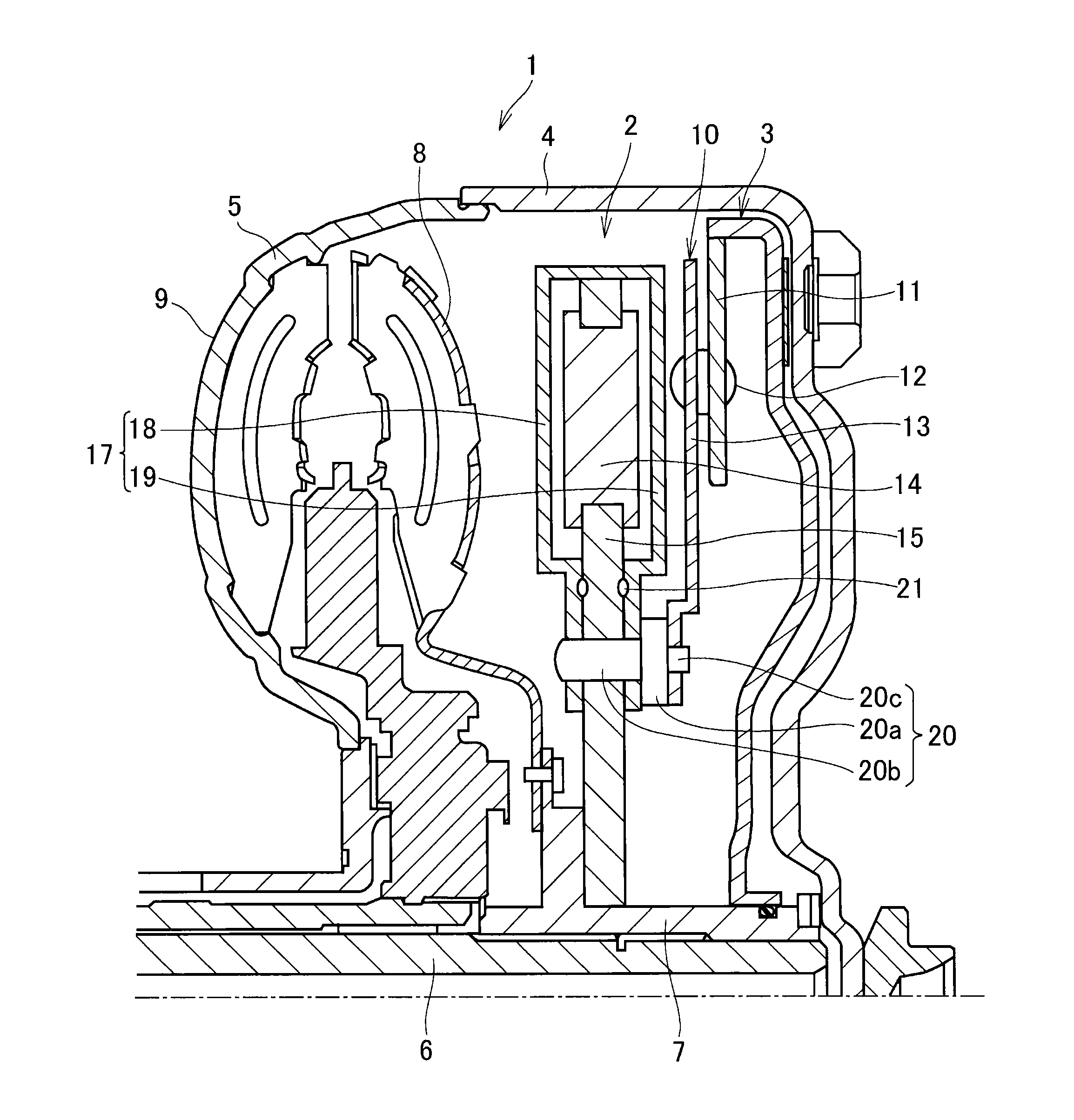
[0023]The following description relates to the vibration damping device of the present invention, and a principle of vibration damping action is similar to those taught by the prior art documents cited in the background. Turning first to FIG. 1, there is shown a torque converter 1 according to the first example having a torsional vibration damping device 2 and a lockup clutch 3. A front cover 4 is connected to a pump shell 5 to form a housing of the torque converter 1, and an input shaft 6 penetrates through a center axis of the housing. In order to transmit torque to a not shown transmission, a turbine hub 7 is fitted onto the input shaft 6 to be rotated integrally therewith while being connected to a turbine runner 8 and a lockup clutch 3. Further, the torsional vibration damping device 2 is fitted onto the turbine hub through a spline.

[0024]As known in the conventional art, the turbine runner 8 is disposed to be opposed to a pump impeller 9 and rotated by a spiral oil flow create...


PUM


Abstract

A vibration damping device in which a covering member can be fixed firmly to a rotary member by a rivet is provided. In the vibration damping device, a pendulum mass 14 is held in a rotary member 15, and a casing 17 is fixed to the rotary member 15 by a rivet 20. The rivet 20 comprises a head 20a, a first shaft 20b and a second shaft 20c. The first shaft 20a penetrates through a first casing member 18, the rotary member 15 and the second casing member 19, and a tail thereof is expanded to fasten those members. The second shaft 20c penetrates through a driven member, and a tail thereof is expanded to fasten the driven member to the rotary member 15.

Description

[0001]The present invention claims the benefit of Japanese Patent Application No. 2014-132948 filed on Jun. 27, 2014 with the Japanese Patent Office, the disclosure of which is incorporated herein by reference in its entirety.BACKGROUND[0002]1. Field of the Invention[0003]The present invention relates generally to the art of a vibration damping device for damping torsional vibrations, and especially to a vibration damping device having a pendulum mass held in a rotary member and oscillated by torque pulses of the rotary member.[0004]2. Discussion of the Related Art[0005]Rotary members such as a drive shaft and gears involving torque transmission between a prime mover to a driven member are vibrated inevitably by torque pulses, load fluctuations, friction etc. Vibration frequency of the rotary member is changed in accordance with a rotational speed, and vibration amplitude is increased by a resonance between an intrinsic vibration frequency of the rotary member itself and the torque ...

Claims


Application Information

Patent Timeline
IPC IPC(8): F16F15/14
CPCF16F2230/30F16H2045/0221F16H2045/0263F16F15/145
Inventor MIYAHARA, YUHONDA, ATSUSHITSUKANO, HUSAHIROMATSUMOTO, MORIHIROSEKIGUCHI, TADASHIHORITA, SHUHEI
Owner TOYOTA JIDOSHA KK
Why Eureka
Try Eureka