Fiber optic probe for remote spectroscopy

a fiber optic probe and remote spectroscopy technology, applied in the field of fiber optic probes, can solve the problems of limited useful depth of focus of the probe, no advantage of collecting light, and difficult manufacturing, and achieve the effect of improving throughpu

Active Publication Date: 2015-12-31
PAWLUCZYK RAFAL +1
View PDF2 Cites 32 Cited by
  • Summary
  • Abstract
  • Description
  • Claims
  • Application Information

AI Technical Summary

Benefits of technology

[0046]The fiber optic probe described herein readily lends itself to miniaturization. For example, which is not to be construed as limiting in any manner, the probe may have an overall diameter below 4 mm and a rigid length of 30 mm. As would be understood by one of skill in the art, longer versions of such probes may be fabricated as required by adding an additional section of rigid tube over the excitation and collection fibers. Reduction in size of certain components may be used to achieve an overall probe diameter for example, but not limited to, below 2 mm or below 1 mm or below 0.5 mm, or any amount therebetween. At that size, the rigid section of the probe may be, for example which is not to be considered limiting, be less than 10 mm long or less than 5 mm long or less than 2 mm long, or any amount therebetween, thus enabling in-vivo endoscopic applications.
[0047]Another aspect of the present disclosure, leading to further improvement in throughput, is the arrangement of the collection fibers at the distal end of the probe into a linear array corresponding closely to the entrance slit of the spectrograph. This ensures that radiation from all collection fibers enters the spectrograph.

Problems solved by technology

As a result there is no advantage to collecting light which will not be later captured by the spectrograph.
As a result the useful depth of focus of the probe is limited.
Such components are difficult to manufacture and their performance varies with wavelength, affecting the relative strength of the Raman peaks observed.
The physical layout of the probe makes it also fairly bulky, acceptable for industrial and lab use, but not practical for biomedical in-vivo work.
The tradeoff is that the collection bundle becomes larger and requires additional reformatting at the instrument input.
However, it is difficult to fabricate high performance filters on optical fiber faces with current technology.
In addition, such filters perform sub-optimally as they are placed in converging light beams.
Thus, these probes could not match the performance of imaging probes.

Method used


Image

  • Fiber optic probe for remote spectroscopy
  • Fiber optic probe for remote spectroscopy
  • Fiber optic probe for remote spectroscopy

Examples


Embodiment Construction

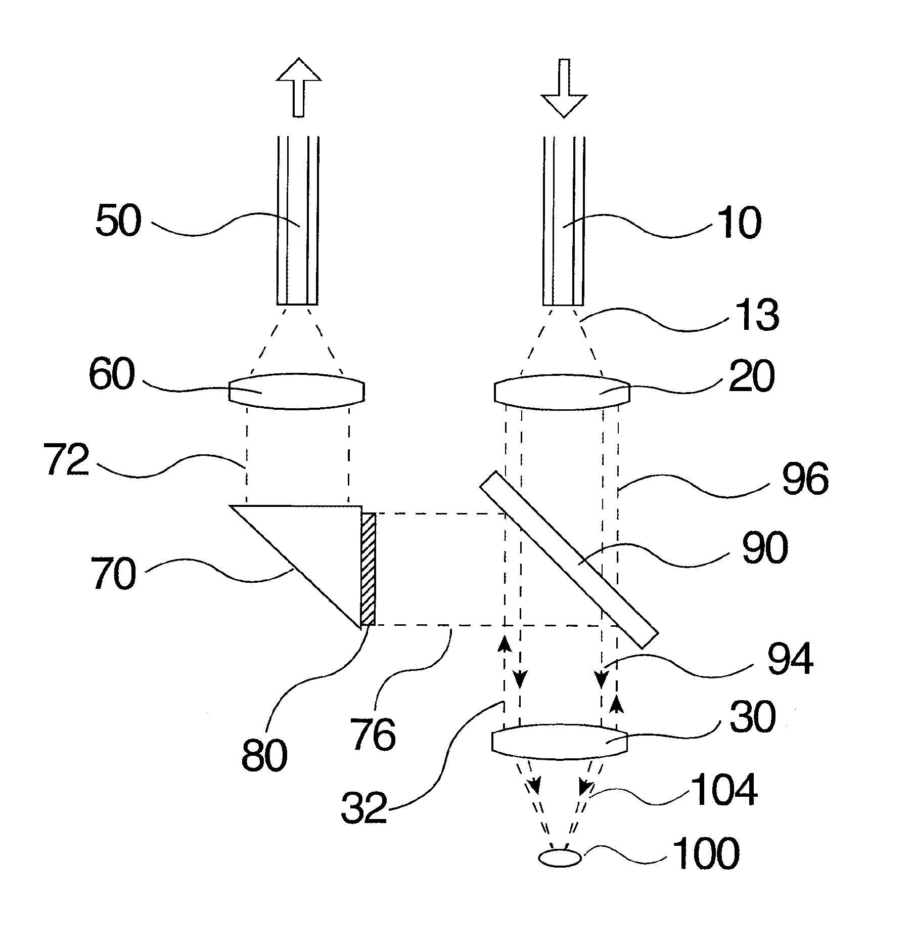
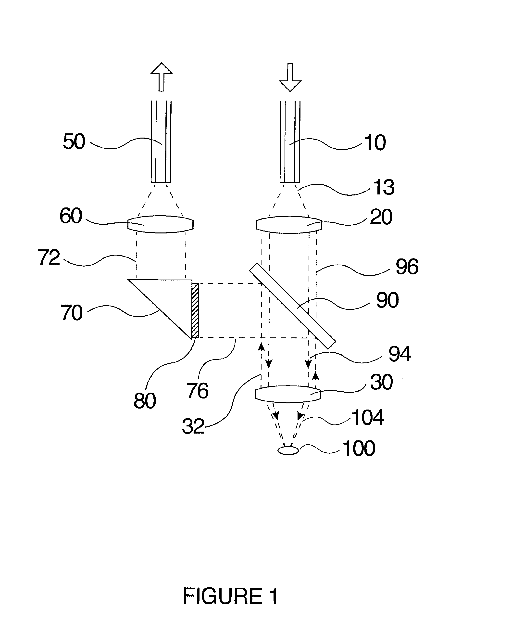
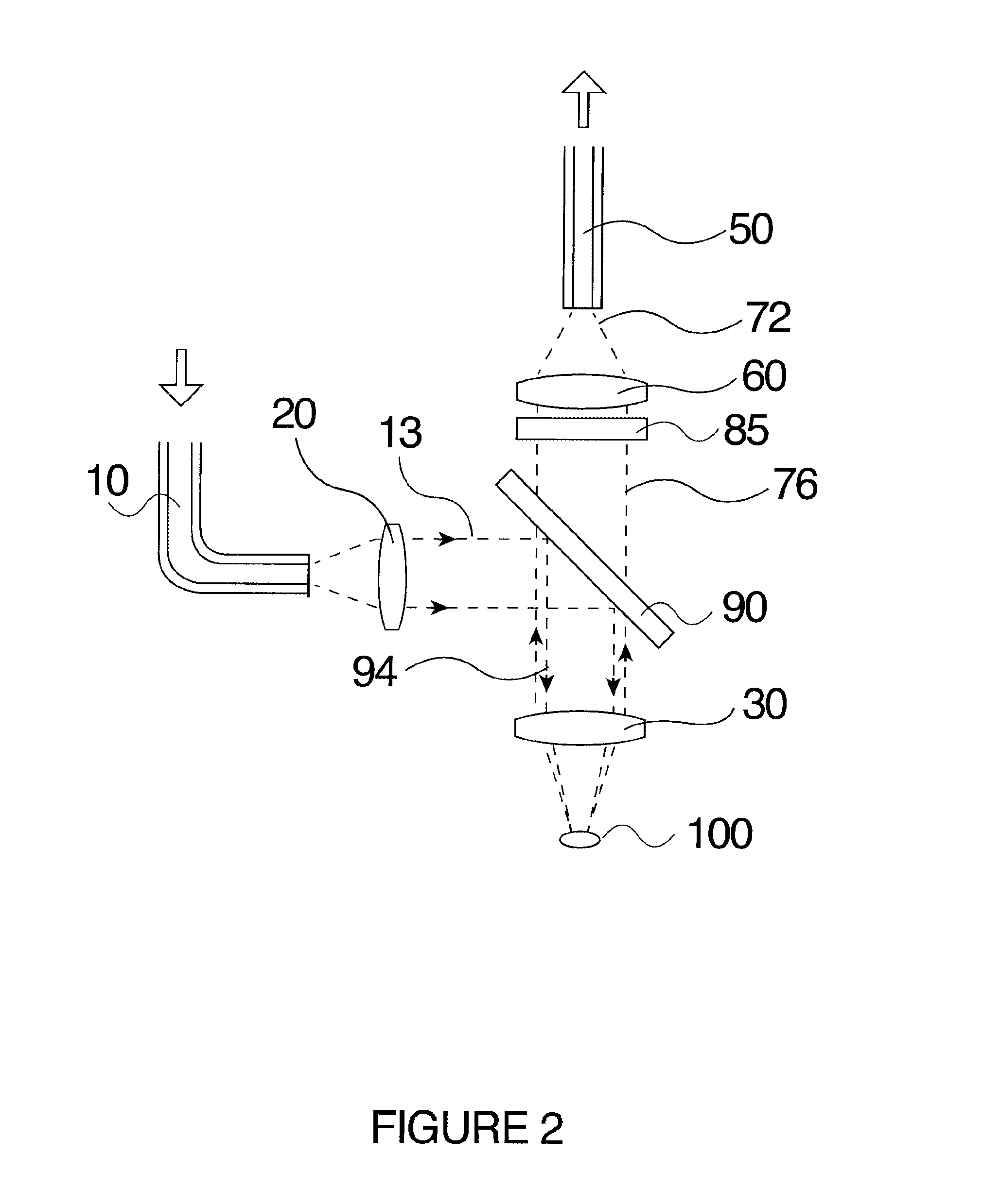
[0069]The present invention relates to a fiber optic probe. The fiber optic probe may be lensed and filtered and comprise two coaxial but optically isolated and independent beam paths.

[0070]The following description is of a preferred embodiment.

[0071]The headings provided are not meant to be limiting of the various embodiments of the invention. Terms such as “comprises”, “comprising”, “comprise”, “includes”, “including” and “include” are not meant to be limiting. In addition, the use of the singular includes the plural, and “or” means “and / or” unless otherwise stated. Unless otherwise defined herein, all technical and scientific terms used herein have the same meaning as commonly understood by one of ordinary skill in the art.

[0072]The present invention provides a fiber optic probe assembly comprising, a first optical system and a second optical system. The first and second optical systems are optically isolated and are comprised of separate optical components. The first optical sys...


PUM


Abstract

A fiber optic probe assembly is provided. The probe comprises a first optical system and a second optical system, a delivery light guide comprising one or more than one delivery optical fiber for transmitting excitation radiation from a radiation source disposed at a proximal end of the light guide to the first optical system. The first optical system comprising one or more than one first optical element for forming a substantially collimated illumination beam from the excitation radiation. An optically opaque tubular sleeve is fitted over the first optical system to optically isolate the first optical system and the delivery light guide from the second optical system. The second optical system comprising one or more than one second optical element for gathering optical radiation scattered from a sample and forming the optical radiation into a collection beam. A collection light guide comprising one or more than one collection optical fiber receives the collection beam and transmits the collection beam to an analyzer. The first and second optical systems are disposed within a housing so that an emission cone of the first optical system and an acceptance cone of the second optical system substantially overlap. A spectroscopic measurement system comprising the optic fiber probe is also provided.

Description

FIELD OF INVENTION[0001]The present invention relates to a fiber optic probe. The fiber optic probe may be lensed and filtered and comprise two coaxial but optically isolated and independent beam paths.BACKGROUND OF THE INVENTION[0002]Quick and reliable chemical analysis of substances is a critical requirement in many industries. Many currently available analytical techniques involve an interaction of optical radiation with the sampled substance, where the molecules of the sample absorb at least some of the energy from the incident radiation. This energy can then be re-emitted through: diffuse reflectance (strong signal at the same wavelength, almost instantaneous); Raman scattering (very weak signal at a slightly shifted wavelength, almost instantaneous); and fluorescence (weak signal at a longer wavelength, time delayed, decaying with time).[0003]Raman spectroscopy, in particular, is suitable for chemical analysis and monitoring. Raman frequency shifts are specific to the molecula...

Claims


Application Information

Patent Timeline
Patent Type & Authority Applications(United States)
IPC IPC(8): G01J3/02G01J3/28G01J3/44
CPCG01J3/0243G01J3/021G01J3/0208G01J3/0218G01J3/0221G01J3/4412G01N21/65G01N2021/4742G01N2021/656G01J3/2823G01J3/44
Inventor PAWLUCZYK, RAFALFOURNIER, PAUL
Owner PAWLUCZYK RAFAL
Why Eureka
Try Eureka