Dc-dc converter

a converter and converter technology, applied in the direction of electric variable regulation, process and machine control, instruments, etc., can solve the problems of increasing switching loss, generating conduction loss in the transformer and the switching element, and not contributing to the power of current, so as to reduce the size, weight and cost of the converter, the effect of enhancing power conversion efficiency

Active Publication Date: 2015-12-31
MITSUBISHI ELECTRIC CORP
View PDF9 Cites 11 Cited by
  • Summary
  • Abstract
  • Description
  • Claims
  • Application Information

AI Technical Summary

Benefits of technology

[0013]In a DC-DC converter according to the present invention, the current circulating in the transformer, the switching elements and the series reactor can be decreased without adding any extra parts, and soft switching operation of the primary-side switching elements can be performed, so that power conversion efficiency can be enhanced, and the converter can be reduced in size, weight and cost.

Problems solved by technology

However, a circulation current that circulates between the primary side switching elements and the transformer arises in a power non-transmission period.
Although the circulation current produces an effect of making the primary side switching elements perform soft switching operation, the current does not contribute to the power transmission but generates conduction loss in the transformer and the switching elements in the primary side thereof.
However, the primary-side semiconductors perform hard switching in the PMW control, which will resultantly increase switching loss.

Method used


Image

  • Dc-dc converter
  • Dc-dc converter
  • Dc-dc converter

Examples


embodiment 1

[0022]Hereinafter, a DC-DC converter according to Embodiment 1 of the present invention will be explained based on the drawings.

[0023]To begin with, a primary-side phase-shift type DC-DC converter, underlying the present invention, with a full-bridge inverter and a rectifier circuit combined together will be explained referring to FIG. 1 and FIG. 2.

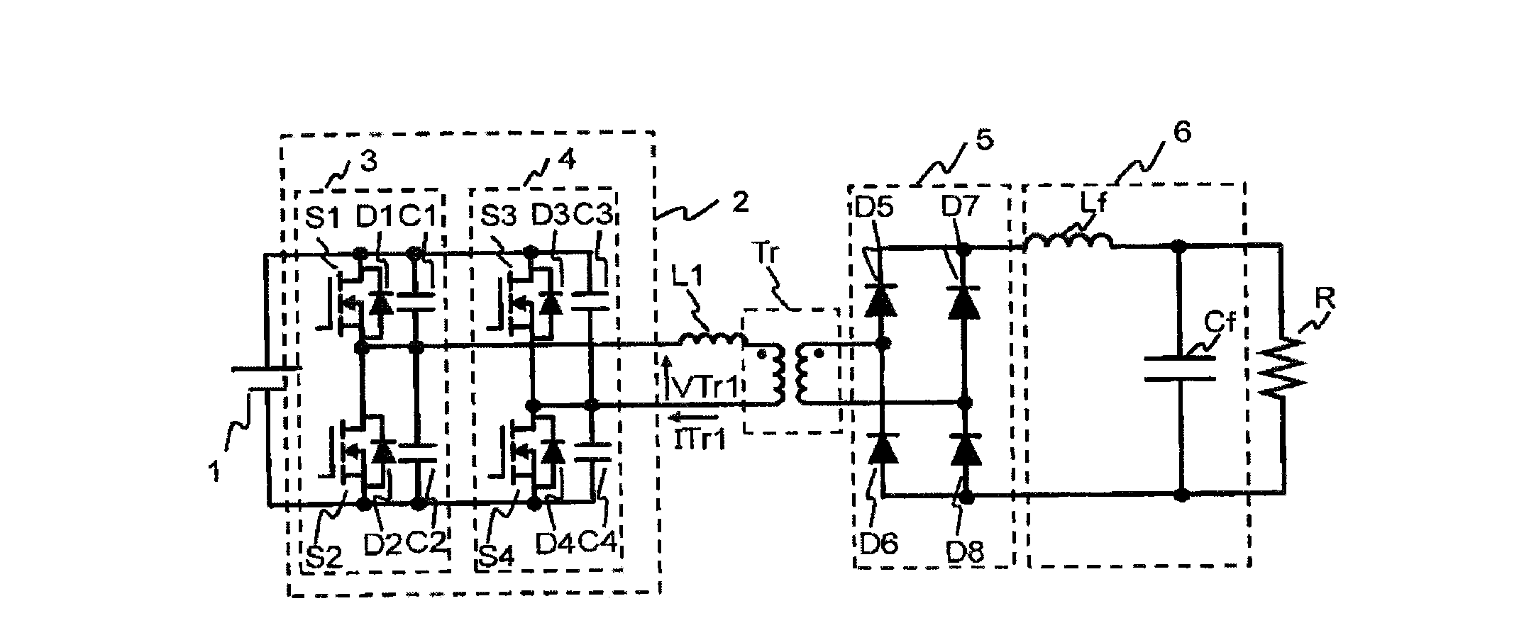
[0024]In FIG. 1, the full-bridge inverter 2 (hereinafter simply referred to as an inverter) converts a DC voltage from a DC power supply 1 into a high-frequency AC voltage and inputs the voltage to a transformer Tr. A rectifier circuit 5 rectifies the high-frequency AC voltage output from the transformer Tr. An output smoothing filter 6 constituted of a smoothing reactor (choke coil) Lf and a smoothing capacitor Cf removes high-frequency components from the voltage output from the rectifier circuit 5, and the resultant DC voltage is supplied to a load R.

[0025]The full-bridge inverter 2 comprises a circuit constituted of a reference phase ...

embodiment 2

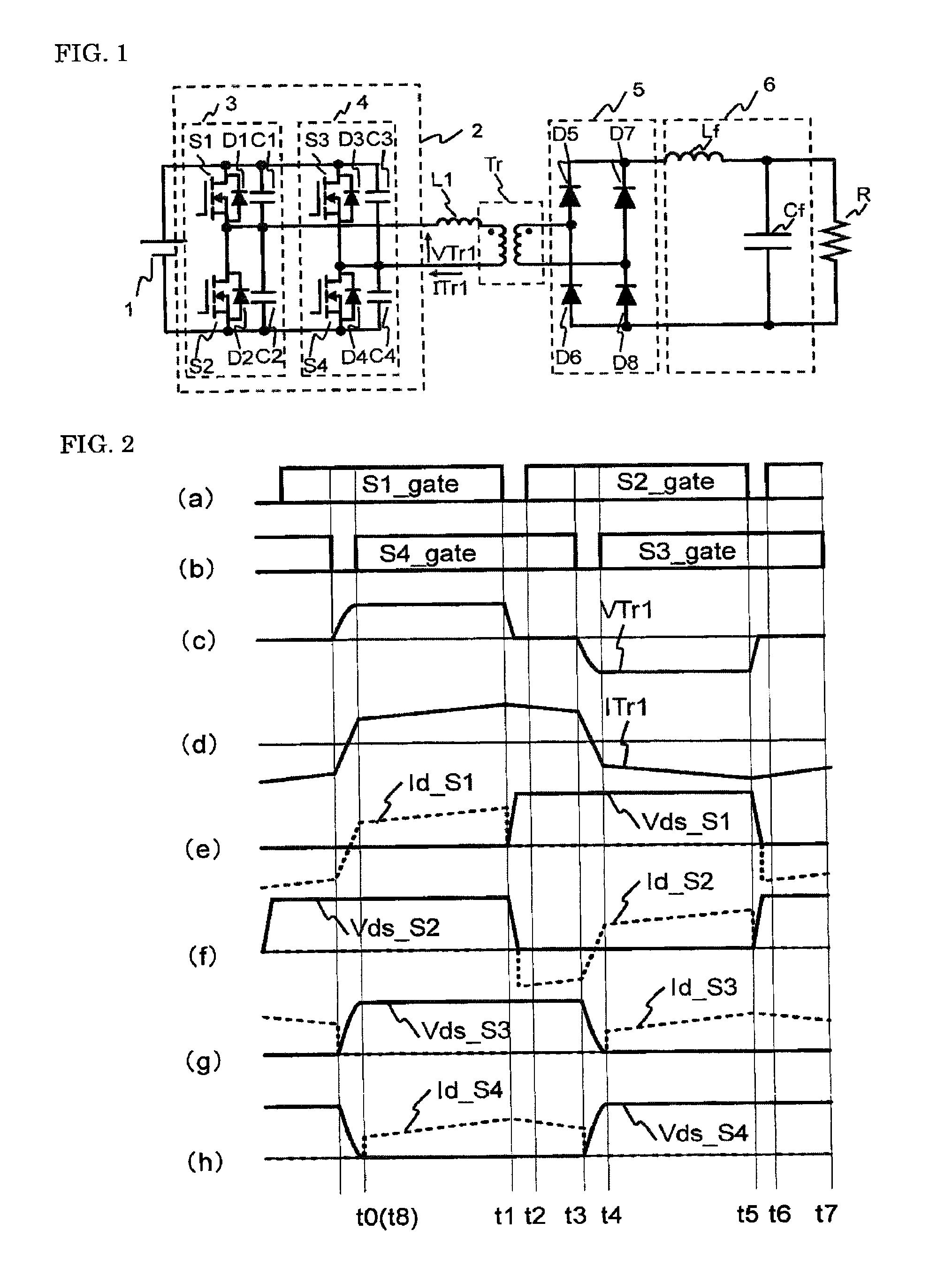
[0068]A DC-DC converter according to Embodiment 2 of the present invention will be explained based on FIG. 5.

[0069]Additionally, it is assumed that the circuit configuration is the same as that in FIG. 1 and MOSFETs are used for the switching elements constituting the full-bridge inverter 2.

[0070]Moreover, (a) to (h) in FIG. 5 show driving signals supplied to the switching elements S1 to S4, the voltage VTr1 input to the transformer Tr, the current ITr1 flowing through the primary coil of the transformer, voltages across the switching elements S1 to S4: Vds-S1 to Vds-S4 (solid lines), and Id-S1 to Id-S4 flowing through S1 to S4 (broken lines), respectively.

[0071]Furthermore, time t0 to time t6 represents switching times of the switching elements S1 to S4; Vds, a drain voltage of each switching element with respect to a source voltage thereof; and Id, a current through each switching element, with the direction flowing therein from the drain positive. Additionally, in FIG. 5, the per...

embodiment 3

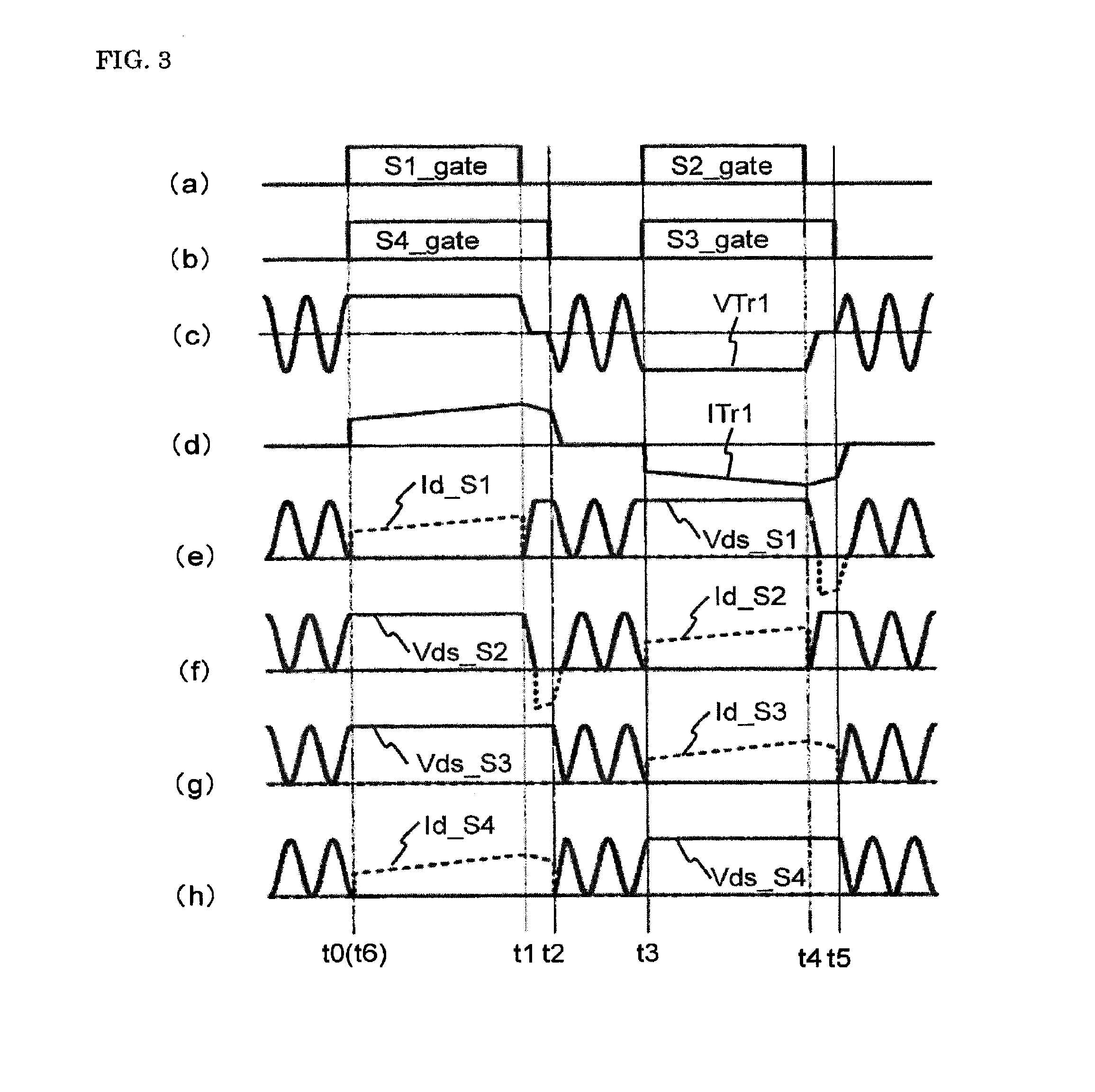
[0085]A DC-DC converter according to Embodiment 3 of the present invention will be explained based on FIG. 6.

[0086]Additionally, it is assumed that the circuit configuration is the same as that in FIG. 1 and MOSFETs are used for the switching elements constituting the full-bridge inverter 2.

[0087]Moreover, (a) to (h) in FIG. 6 show driving signals supplied to the switching elements S1 to S4, the voltage VTr1 input to the transformer, the current ITr1 flowing through the primary coil of the transformer, voltages across the switching elements S1 to S4: Vds-S1 to Vds-S4 (solid lines), and Id-S1 to Id-S4 flowing through S1 to S4 (broken lines), respectively.

[0088]Furthermore, time t0 to t6 represents switching times of the switching elements S1 to S4; Vds, a drain voltage of each switching element with respect to a source voltage thereof; and Id, a current through each switching element, with the direction flowing therein from the drain positive. Additionally, in FIG. 6, the period from...


PUM


Abstract

A DC-DC converter wherein a series reactor and primary-side terminals of a transformer are connected between output terminals of a full-bridge inverter in which each of an upper arm and a lower arm includes a switching element and a freewheel diode, and a rectifier circuit and a filter circuit are connected to secondary-side terminals of the transformer. The DC-DC converter includes a circulation current generation mode in which a circulation current flowing between the transformer and the switching element is generated in a power non-transmission period, and a circulation current interruption mode in which the circulation current is interrupted.

Description

TECHNICAL FIELD[0001]The present invention relates to DC-DC converters including a full-bridge inverter that converts a DC voltage into a high-frequency AC voltage and a rectifier circuit that rectifies its output.BACKGROUND ART[0002]A primary-side phase-shift type DC-DC converter including a full-bridge inverter combined with a rectifier circuit is configured as follows:[0003]That is, the full-bridge inverter comprises a circuit constituted of a reference phase leg and a control phase leg connected in parallel with each other, in which the reference phase leg includes an upper arm including switching element S1, a snubber capacitor C1 connected in parallel to the switching element S1, and a freewheel diode D1 connected in antiparallel to the switching element S1, and a lower arm including a switching element S2, a snubber capacitor C2 connected in parallel to the switching element S2, and a freewheel diode D2 connected in antiparallel to the switching element S2, with the upper arm...

Claims


Application Information

Patent Timeline
Patent Type & Authority Applications(United States)
IPC IPC(8): H02M3/335
CPCH02M3/3376H02M3/33546Y02B70/1491H02M2001/0058Y02B70/10H02M1/0058
Inventor TAKAHARA, TAKAAKIMURAKAMI, SATOSHIKONDO, RYOTAYAMADA, MASAKI
Owner MITSUBISHI ELECTRIC CORP
Why Eureka
Try Eureka