Method of producing surface-treated steel sheet

Inactive Publication Date: 2016-01-07
TOYO KOHAN CO LTD +1
View PDF8 Cites 1 Cited by
  • Summary
  • Abstract
  • Description
  • Claims
  • Application Information

AI Technical Summary

Benefits of technology

The present invention relates to a method for forming metal-oxygen compound layers on a base material, which prevents the occurrence of appearance failures, such as arc spots, on the base material caused by excessive voltages applied to the carrier rolls. The method uses two electrolytic treatment baths, with one bath being an energized conductor roll and the other baths being non-energized rolls. This prevents the voltage from being applied to the carrier rolls, even if there are irregularities on their surfaces, such as deposition of the metal-oxygen compound layers. The method also uses carrier rolls that are not energized conductor rolls, reducing the likelihood of high voltage discharge and the occurrence of arc spots. Overall, the method improves productivity and quality by preventing appearance failures on the base material.

Problems solved by technology

Therefore, problems will arise as below.
Since an excessive voltage is being applied to the energized roll as described above, irregularities due to such deposited substances cause high voltage discharge to locally take place on the energized roll, which may be problematic because the appearance failure such as a trace of discharge (arc spot) occurs on the metal base material.
In addition, the cathode electrolytic treatment as disclosed in Patent Document 1 involves a problem in that the energized roll may be damaged by being applied with an excessive voltage and a problem in that, when the high voltage discharge locally takes place, maintenance of the energized roll will be needed in each case.
Moreover, if a steel sheet formed with an arc spot is used for metal cans or other sensitive products, the arc spot portion will be a defect portion in the surface treatment thereby to induce corrosion resistance failure inside the cans and appearance failure outside the cans.
Furthermore, if the arc spot is serious, the can will get a hole, which may lead to leakage of the contents.
Therefore, as the metal-oxygen compound layer is formed to have a larger thickness, such problems tend to be serious.
It has thus been difficult to increase the thickness of the metal-oxygen compound layer without causing such problems as described above.

Method used


Image

  • Method of producing surface-treated steel sheet
  • Method of producing surface-treated steel sheet
  • Method of producing surface-treated steel sheet

Examples


example 1

[0105]A cold-rolled steel sheet (thickness of 0.2 mm and width of 200 mm) was prepared as a raw sheet.

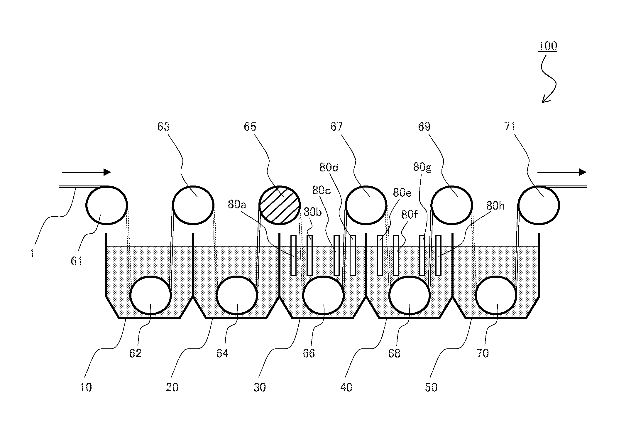
[0106]The prepared steel sheet was electrolytically degreased and then washed with water, and thereafter the surface treatment apparatus 100 illustrated in FIG. 6 was used to perform cathode electrolytic treatment. In the cathode electrolytic treatment, pretreatment was first performed such that: the steel sheet was fed by the carrier roll 61 into the acid pickleing treatment bath 10 filled with sulfuric acid; the steel sheet was pickleed by the sulfuric acid in the acid pickleing treatment bath 10; the steel sheet was then fed out of the acid pickleing treatment bath 10 and fed into the acid pickleing liquid rinsing treatment bath 20 filled with water by the carrier roll 63; and the steel sheet was washed with the water in the acid pickleing liquid rinsing treatment bath 20. Subsequently, the steel sheet was fed by the carrier roll 65 (first roll) into the first electrolytic treatm...

examples 2 and 3

[0124]Surface-treated steel sheets were obtained and evaluated in the same manner as in Example 1 except that the conditions of the total quantity of electricity flowing through the steel sheet and the magnitude of current to the carrier roll 65 (first roll) were changed to those listed in Table 1 when performing the electrolytic treatment for the steel sheet. Results are listed in Table 1.

example 4

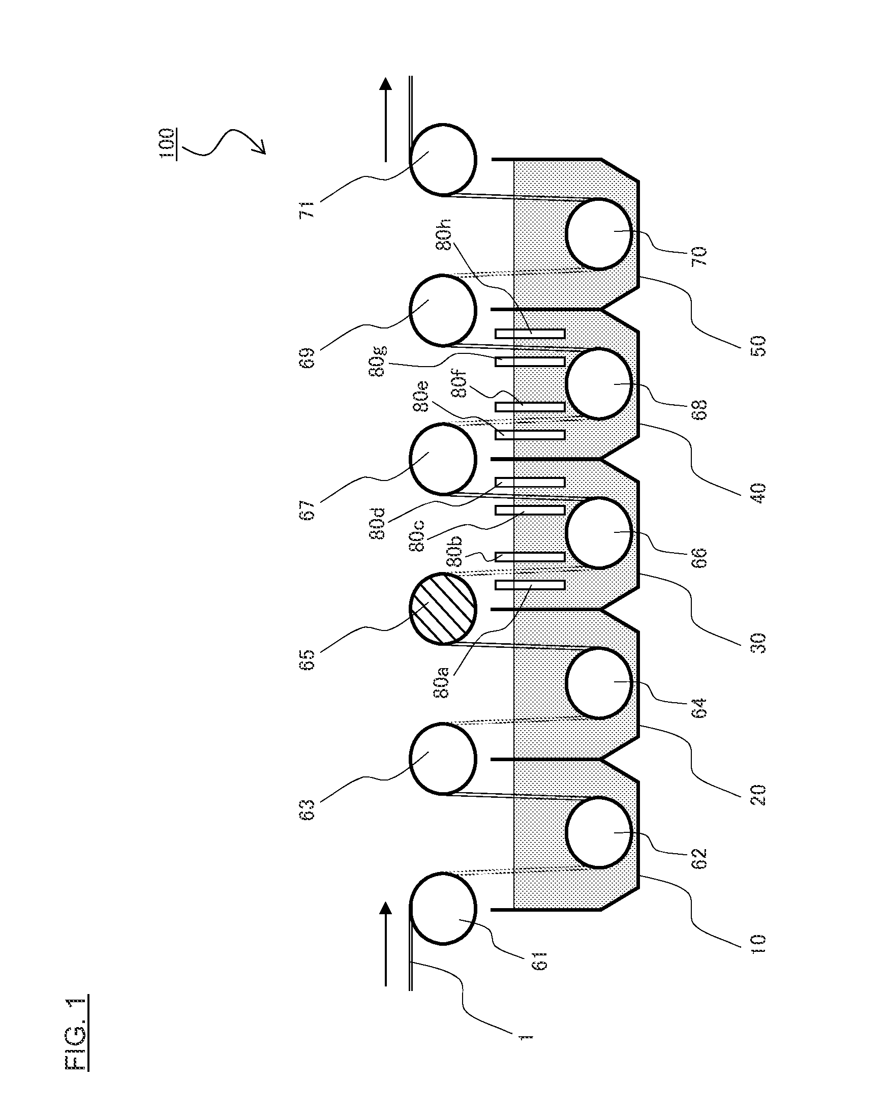
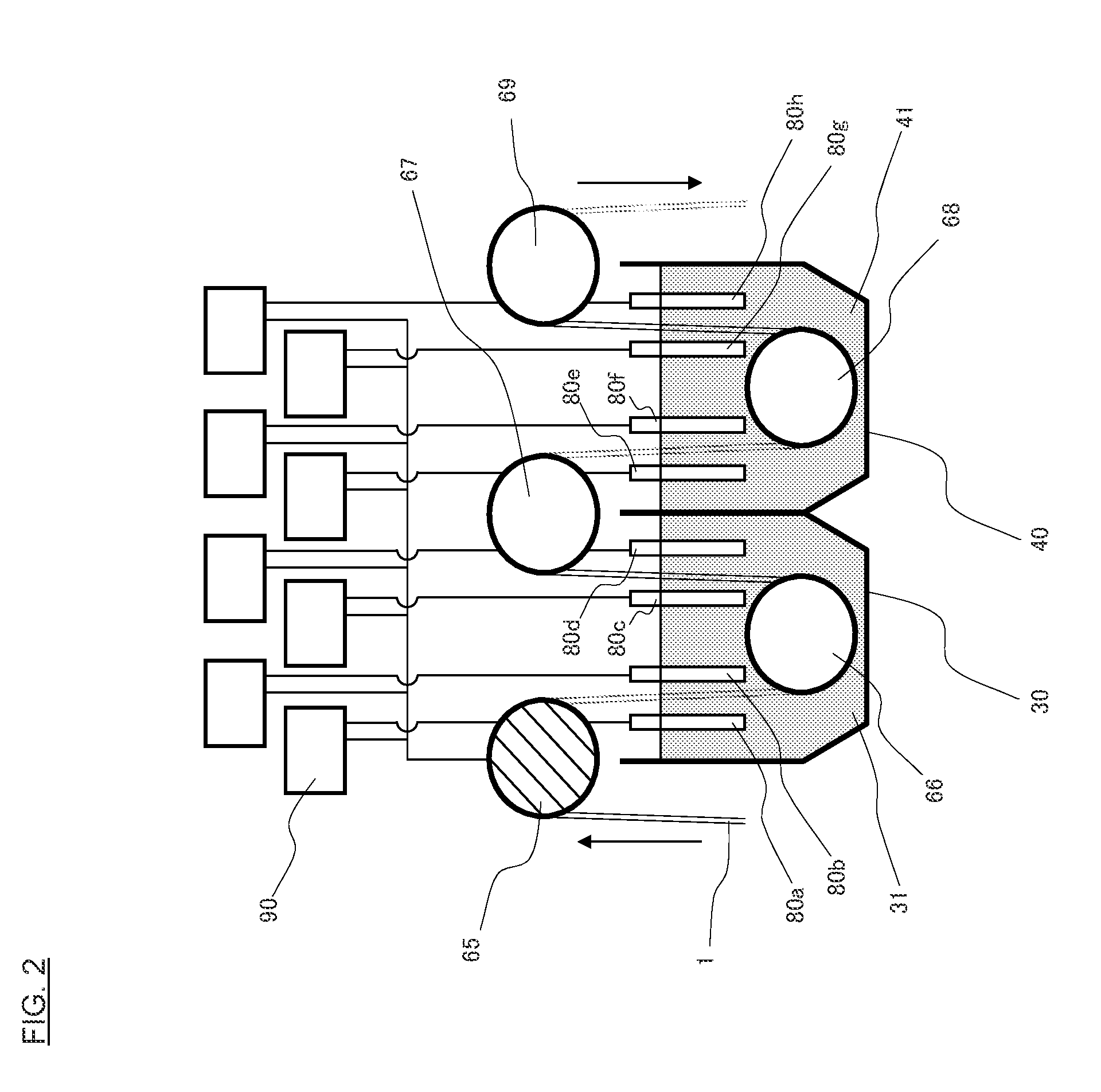
[0125]In Example 4, the surface treatment apparatus 100 illustrated in FIG. 1 and FIG. 2 was used to prepare a surface-treated steel sheet. In Example 4, the same electrolytic treatment liquid as in Example 1 was used as each of the electrolytic treatment liquids 31 and 41 in the first electrolytic treatment bath 30 and the second electrolytic treatment bath 40. In Examples 4 to 6, the electrolytic treatment was also performed while circulating the electrolytic treatment liquids 31 and 41.

[0126]The electrolytic treatment in Example 4 was performed in the first electrolytic treatment bath 30 and the second electrolytic treatment bath 40 to form the metal-oxygen compound layers on the steel sheet under the conditions of: a manufacturing line speed (feeding speed of steel sheet) of 10 m / min; a cycle number of 4; an energizing time for 1 cycle of 1.2 seconds; a total quantity of electricity flowing through the steel sheet of 17 C / dm2; and a magnitude of the current to the carrier roll 6...


PUM

PropertyMeasurementUnit
Thicknessaaaaaaaaaa
Electrical resistanceaaaaaaaaaa

Abstract

A method of producing a surface-treated steel sheet is provided. The method has a step of performing electrolytic treatment thereby to form a layer including a metal-oxygen compound on a surface of a steel sheet. The electrolytic treatment is performed so that the steel sheet is continuously fed into electrolytic treatment baths each including a treatment liquid and an electrode. The treatment liquid contains metal ions. The method is characterized in that: rolls provided for each of the electrolytic treatment baths (a roll for feeding the steel sheet into the electrolytic treatment bath and a roll for feeding the steel sheet out of the electrolytic treatment bath) comprise an energized roll that is electrically connected to a power source for flowing a direct current through the steel sheet and a non-energized roll that is not connected to a power source; and the energized roll is arranged such that, once the metal-oxygen compound has been formed by electrolytic treatment on a surface of the steel sheet to be in contact with the rolls, the metal-oxygen compound and the energized roll are not in contact with each other so as not to generate an arc spot.

Description

BACKGROUND OF THE INVENTION[0001]1. Technical Field of the Invention[0002]The present invention relates to a method of producing a surface-treated steel sheet.[0003]2. Description of the Related Art[0004]A method using chemical conversion treatment is widely employed as a method of forming a layer of which the main constituent is a metal-oxygen compound of metal, such as Zr, Al and Ti, on a metal base material. In the method using chemical conversion treatment, a metal-oxygen compound layer is formed on a metal base material such that: the metal base material is dipped in a treatment liquid; etching treatment is performed for a surface of the metal bate material; the pH in the vicinity of the surface of the metal base material is increased thereby to deposit a metal-oxygen compound on the surface of the metal base material.[0005]According to such a method using chemical conversion, however, the rate of forming the metal-oxygen compound layer depends on the chemical reaction rate in ...

Claims


Application Information

Patent Timeline
IPC IPC(8): C25D9/10C25D3/44C25D3/54C25D5/04C25D7/00
CPCC25D9/10C25D3/44C25D5/04C25D7/00C25D3/54C25D17/10C25D21/12C25D9/04
Inventor YOSHIMURA, KUNIHIROTAGUCHI, NAOMIFUKUTOMI, SATOKOKUROKAWA, WATARUHIROTSU, MUNEMITSUKANAZAWA, SEITARO
Owner TOYO KOHAN CO LTD
Why Eureka
Try Eureka