Sealess, liquid cooled eddy current energy absorption system

a liquid cooled eddy current and energy absorption technology, applied in the direction of braking systems, asynchronous induction clutches/brakes, mechanical equipment, etc., can solve the problems of high temperature, seal failure, and add a level of device complexity, so as to eliminate braking friction, zero maintenance devices, and low temperature operation

Active Publication Date: 2016-01-07
DECONTI JOHN PETER
View PDF1 Cites 5 Cited by
  • Summary
  • Abstract
  • Description
  • Claims
  • Application Information

AI Technical Summary

Benefits of technology

[0012]The result of this unique design is a virtually zero maintenance device due to elimination of braking friction and low temperature operation due to liquid cooling. Furthermore, without dynamic seals, it is a more robust and cost effective device. And by utilizing permanent magnets instead of electromagnetic coils, it is less complicated, lighter and does not require a high amperage draw. Yet another advantage is that it uses magnetically driven pumping, not external pumps, the pumping action is only when braking occurs.

Problems solved by technology

Most of the LCDB's have required a rotational seal, these seals add a level of complexity to the device, and many factors can come into play to cause these seals to fail.
A limited thermal mass and an unlimited absorption of energy results in temperatures that increase to high levels.
In air cooled friction brakes, high temperatures result in excessive wear of friction material, increased thermal stresses, and decreased capacity to absorb energy (brake fade).
Yet another negative of air-cooled friction brakes is the pollution they cause.
In air cooled eddy current brakes, although there is no wear since there is no friction, however, there is still brake fade and high thermal stresses.
In both cases, high thermal stresses result in failures of rotors and drums.
Each of these patents was an improvement over the previous ones, and one problem they all had in common was creating a cost effective means of sealing them.
Seals can be damaged by many things, such as lack of lubrication, contaminants in the coolant, heat, pressure, or velocity.
In actual use, vibration can also be an issue to make sealing difficult.
However, quality control and inspection are intangible expenses that are easily overlooked, which will result in product failures.
These designs do have components that wear during normal use, they require external pumps to flow coolant, and they have a flow path that creates a temperature differential in the wear surfaces which results in thermal distortion and a pulsation in torque output.
Like other air cooled brakes, they get hot and they experience brake fade and thermal stresses.
They also have parasitic windage losses, which in trucking driveline use results in lower fuel economy.

Method used


Image

  • Sealess, liquid cooled eddy current energy absorption system
  • Sealess, liquid cooled eddy current energy absorption system
  • Sealess, liquid cooled eddy current energy absorption system

Examples


Embodiment Construction

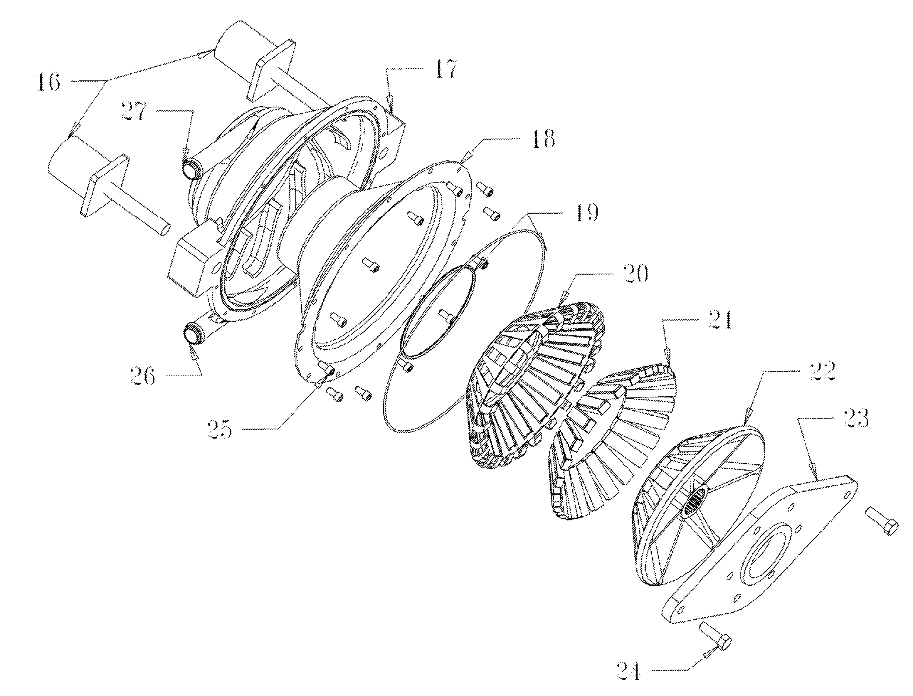
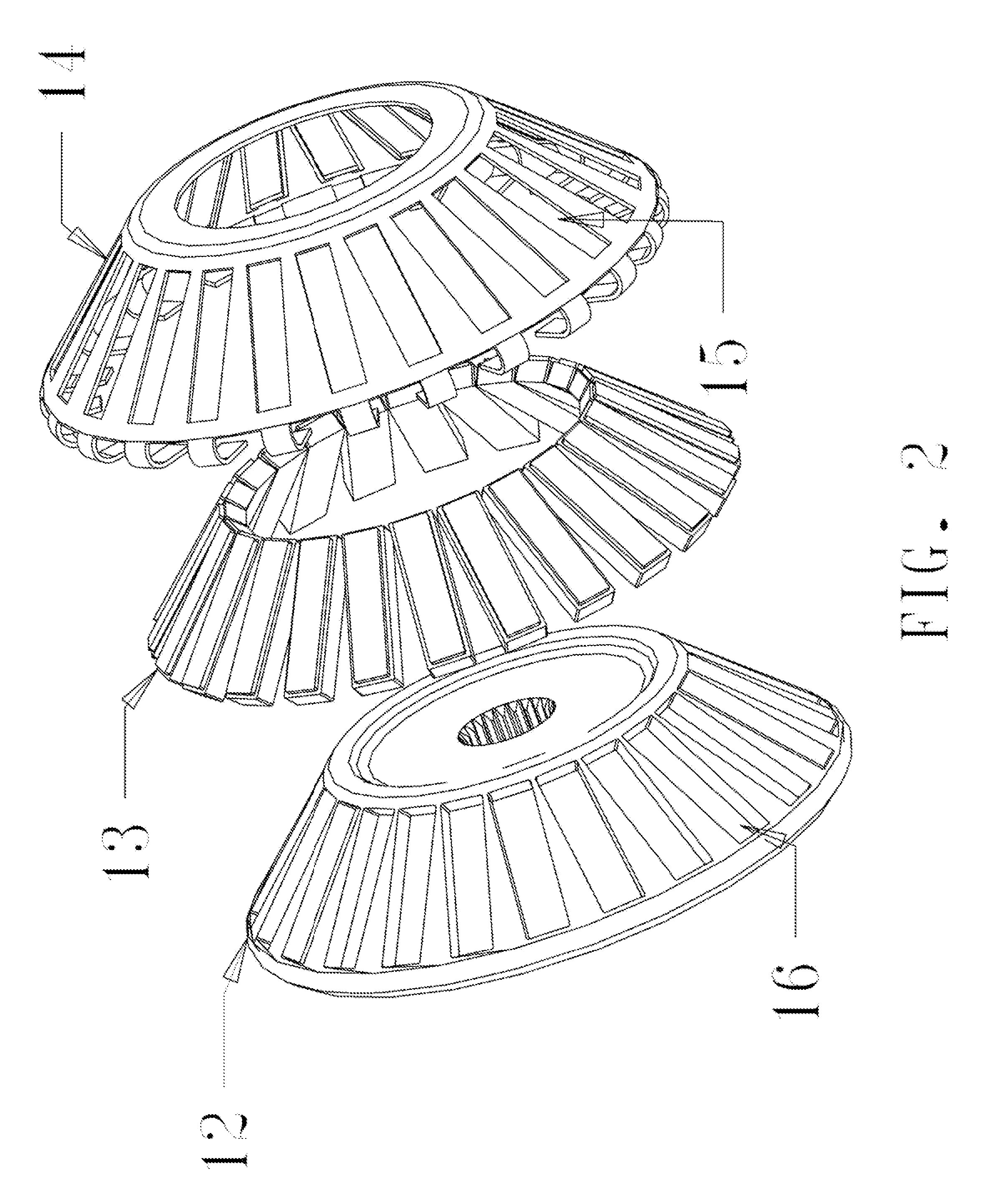
[0022]Braking is controlled by positioning the stationary cooling member(s) closer to or further from the rotating magnets. Coolant flow can be created by convection, or by use of ferromagnetic fluids and their interaction with the rotating magnets, and / or by use of a magnetic pump drive arrangement. The coolant flow path is matched to the magnet placement, in a spiral path, or a straight path if the design is to be implied. Hose connections are made to the stationary member, no rotating seals are needed. Braking energy is a function of RPM, mean effective radius, magnet strength, and distance between the rotor and the stationary cooling member.

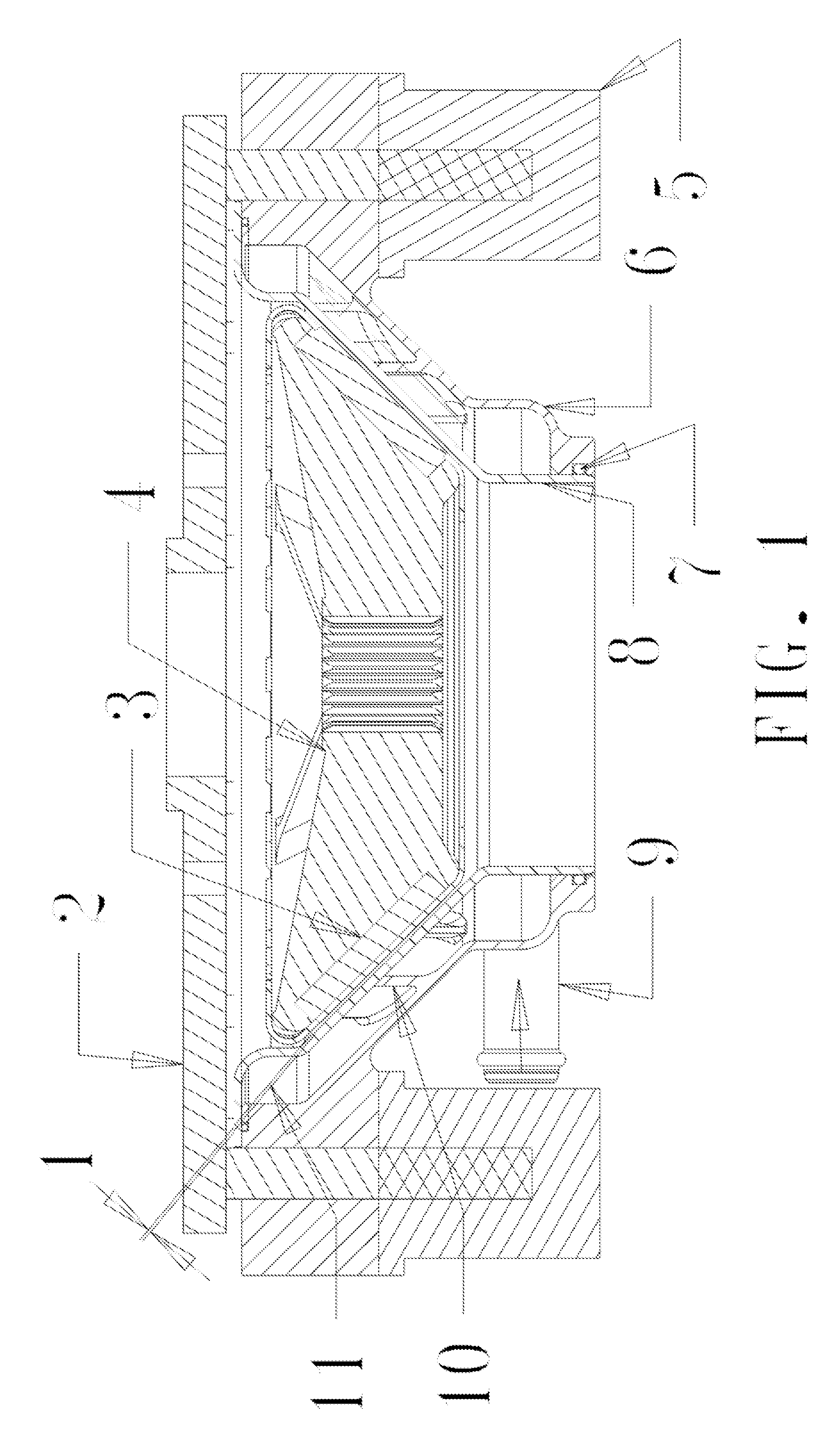
[0023]FIG. 1 shows a crossectional drawing of an exemplary, fully assembled liquid cooled eddy current energy absorbing device. 1 refers to the operating gap when the device is fully engaged. The smaller the gap 1 the greater the braking torque. Gap 1 is increased to vary the braking or to turn it off completely. The Torque Reaction Adapter ...


PUM


Abstract

The disclosed apparatus relates to a non-frictional, rotational, continuous energy absorbing device utilizing internal liquid cooling and having no dynamic seals. The apparatus is comprised of a rotor assembly containing magnets, cooling chambers containing magnetically driven impellers, actuators to adjust the axial positioning of said chambers, and other variations of the apparatus including an air-cooled design and additional friction braking. Braking torque is generated through shearing of eddy currents as the cooling chambers are moved axially closer to the rotor by actuators. The same action also drives magnetically driven impellers, resulting in coolant flow. Braking energy absorption increases as does coolant flow as the distance between the cooling chambers and the rotor is decreased. As the distanced between the rotor and cooling chambers increase, both energy absorption and coolant flow decrease to zero. The coolant flows from the cooling chambers to a heat exchanger to dissipate the energy.

Description

REFERENCE CITED[0001]US PATENT DOCUMENTS744,423November 1903Steckel3,488,535January 1970Baermann5,003,839April 1991DeConti5,358,077October 1994DeConti6,478,126November 2002Drecq8,196,720June 2012DeConti20,130,234,542September 2013Li20,130,341,136December 2013Boonpongmanee62 / 020,058Jul. 2, 2014DeContiBACKGROUND OF THE INVENTION[0002]1. Field of the Invention[0003]The present invention relates to a rotational energy absorbing device that incorporates internal liquid cooling and utilization of eddy currents from permanent magnets.[0004]2. Description of Prior Art[0005]Eddy current brakes (ECB's) have been around for many years, mostly air-cooled. The air cooled ECB's usually use cast iron or steel for rotor materials, which absorb the thermal energy created into its mass, and most of them utilize a fan designed into the rotors to create windage to enhance cooling. Liquid Cooled Disc Brakes (LCDB's) have also been around for years, utilizing internal cooling. LCDB's have been made with ...

Claims


Application Information

Patent Timeline
Patent Type & Authority Applications(United States)
IPC IPC(8): H02K49/04F16D63/00H02K49/10
CPCH02K49/04H02K49/10F16D63/002B60T13/586H02K9/19H02K5/203
Inventor DECONTI, JOHN, PETER
Owner DECONTI JOHN PETER
Why Eureka
Try Eureka