
Mapping ablation catheter

a catheter and catheter technology, applied in the field of mapping ablation catheters, can solve the problems of difficult to adjust the position of the catheter stably, the inability to correct the heartbeat, and the difficulty of a catheter with a plurality of monitoring electrodes, so as to increase the contact area, facilitate the operation of the catheter, and facilitate the operation.

Active Publication Date: 2016-01-14
KOREA UNIV RES & BUSINESS FOUND
View PDF3 Cites 2 Cited by
  • Summary
  • Abstract
  • Description
  • Claims
  • Application Information

AI Technical Summary

Benefits of technology

The present invention relates to a mapping ablation catheter for treating lesion regions in the heart. The catheter has a monitoring electrode, liquid discharge holes, and an ablation electrode arranged in consecutive order, allowing for stable operation even when the catheter position changes slightly due to the heart beat. The catheter can detect and remove lesion regions simultaneously using multiple electrodes, thus minimizing mapping and allowing for efficient and effective treatment.

Problems solved by technology

However, if there is something wrong with the electric signal flow, a correct heart beat cannot be carried out.
However, due to the heart beat, it is difficult to adjust the position of the catheter stably so as to make the ablation electrode contact with the lesion precisely.
Meanwhile, in case that a plurality of monitoring electrodes for detecting lesion region are attached on the distal end, as can be seen in KR Patent 10-0949436, a catheter is not provided with ablation electrodes and therefore it is difficult of a catheter having a plurality of monitoring electrodes to perform both a mapping and an ablation.

Method used


Image

  • Mapping ablation catheter
  • Mapping ablation catheter
  • Mapping ablation catheter

Examples


first embodiment

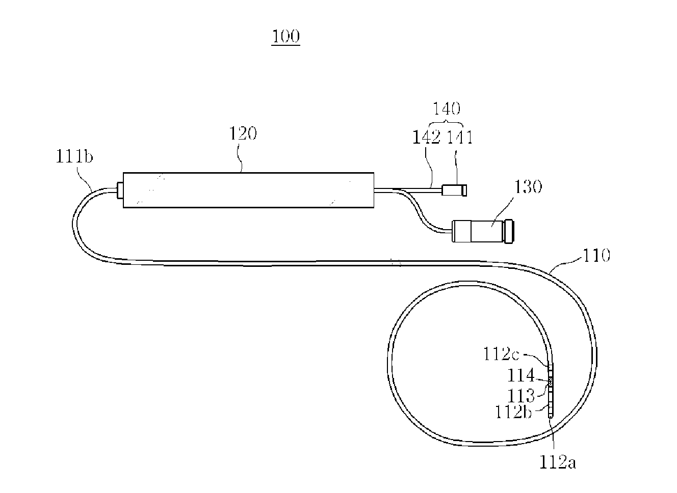
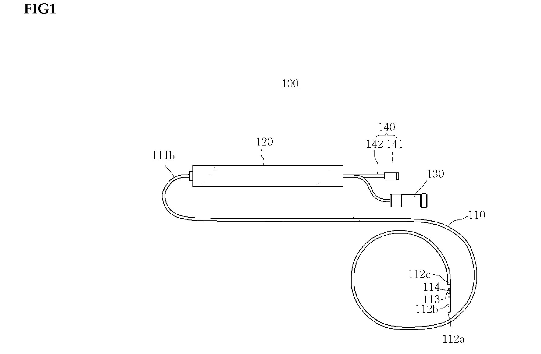
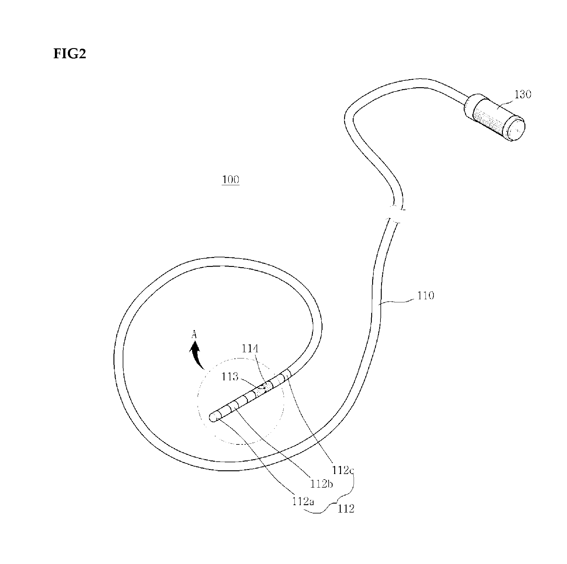
[0038]As shown in FIG. 1, the mapping ablation catheter 100 according to the present embodiment comprises a catheter conduit 111, a monitoring electrode unit 112, an ablation electrode 114, a hand manipulation unit 120, a current application unit 130 and a liquid supply unit 140. The catheter 100 according to the present embodiment can be inserted into the cardiac organ through a blood vessel and remove a lesion region (X) from the cardiac organ without need to perform laparotomy about the entire part on which a surgery is required.

[0039]For clarity's sake, based on a position of an operator during operation, a portion of the catheter conduit 111 near an operator is referred to as a proximal part and a portion of the catheter conduit 111 away from an operator is referred to as a distal part of the catheter conduit 111.

[0040]It is preferable that the catheter conduit 111 according to the present embodiment has a length by which the catheter conduit can be inserted into the body organ...

second embodiment

[0072]As shown in FIG. 5, a mapping ablation catheter 200 according to the second embodiment comprises a catheter conduit 210, a plurality of monitoring electrodes 211, a plurality of ablation electrodes 213, a hand manipulation unit 220 and a liquid supply unit 230. Preferably, in the embodiment, the catheter conduit 210 is made of insulation material to prevent current applied to the plurality of ablation electrodes 213 and the plurality of monitoring electrodes 211 from flowing.

[0073]The catheter 200 according to the present embodiment is configured in such a manner that the catheter conduit 210 is inserted into the cardiac organ through a blood vessel, that a mapping is performed on the plurality of lesion regions (X) by the plurality of monitoring electrodes 211 on the distal portion 210a of the catheter conduit 210, and that the plurality of lesion regions which are in contact with the plurality of ablation electrodes 213 can be removed simultaneously by the plurality of the a...


PUM


Abstract

A mapping ablation catheter is provided comprising: a catheter conduit having a hollow inner space in which a guide member is disposed; a monitoring electrode unit arranged to surround the outer circumferential surface of the distal portion of the catheter conduit and perform a mapping on the lesion region by being in side-contact with a cardiac organ; an ablation electrode unit arranged to be spaced apart from the monitoring electrode unit and surround the outer circumferential surface of the distal portion of the catheter conduit and which removes the lesion region; a plurality of liquid discharge holes arranged on the outer circumferential surface of the ablation electrode; a current application unit which applies current to the monitoring electrode unit and the ablation electrode unit; and a liquid supply unit having a liquid supply tube, one end of the liquid-supply tube connected to the liquid discharge holes in the catheter conduit.

Description

TECHNICAL FIELD[0001]The present invention relates to a mapping ablation catheter, in particular to a mapping ablation catheter which performs a catheter operation stably by increasing a contact area between lesion region and ablation electrode for removing lesion region.BACKGROUND ART[0002]Heart beat is performed when a muscle of cardiac organ is stimulated in consecutive order by an electric signal generated periodically from a portion of cardiac organ. However, if there is something wrong with the electric signal flow, a correct heart beat cannot be carried out. This is so-called cardiac arrhythmia.[0003]Fibrillation of heart is the most common continuous arrhythmia and may increase heart rate up to 100 to 175 per minute or more. Fibrillation of heart may cause the frequency of symptom (e.g., atrial flutter, not normal contraction) to be high and may be linked to various aftereffects such as stroke, blood pooling, blood clot, etc.[0004]Treatment of cardiac arrhythmia was quite ch...

Claims


Application Information

Patent Timeline
Patent Type & Authority Applications(United States)
IPC IPC(8): A61B18/14A61B5/04A61B5/042
CPCA61B18/1492A61B5/04A61B5/0422A61B2018/00083A61B2018/1472A61B2018/00577A61B2018/00839A61B2017/00053A61B2218/002A61B2018/00351A61B2018/00029A61M25/0105A61B5/24A61B5/287A61B18/12A61B18/14A61M25/01
Inventor KIM, YOUNG, HOON
Owner KOREA UNIV RES & BUSINESS FOUND
Learn More