

Apparatus for manufacturing light guide plate
- Summary
- Abstract
- Description
- Claims
- Application Information
AI Technical Summary
Benefits of technology
Problems solved by technology
Method used
Image

Examples
Embodiment Construction
[0046]The present disclosure will be further described with reference to the accompanying drawings.
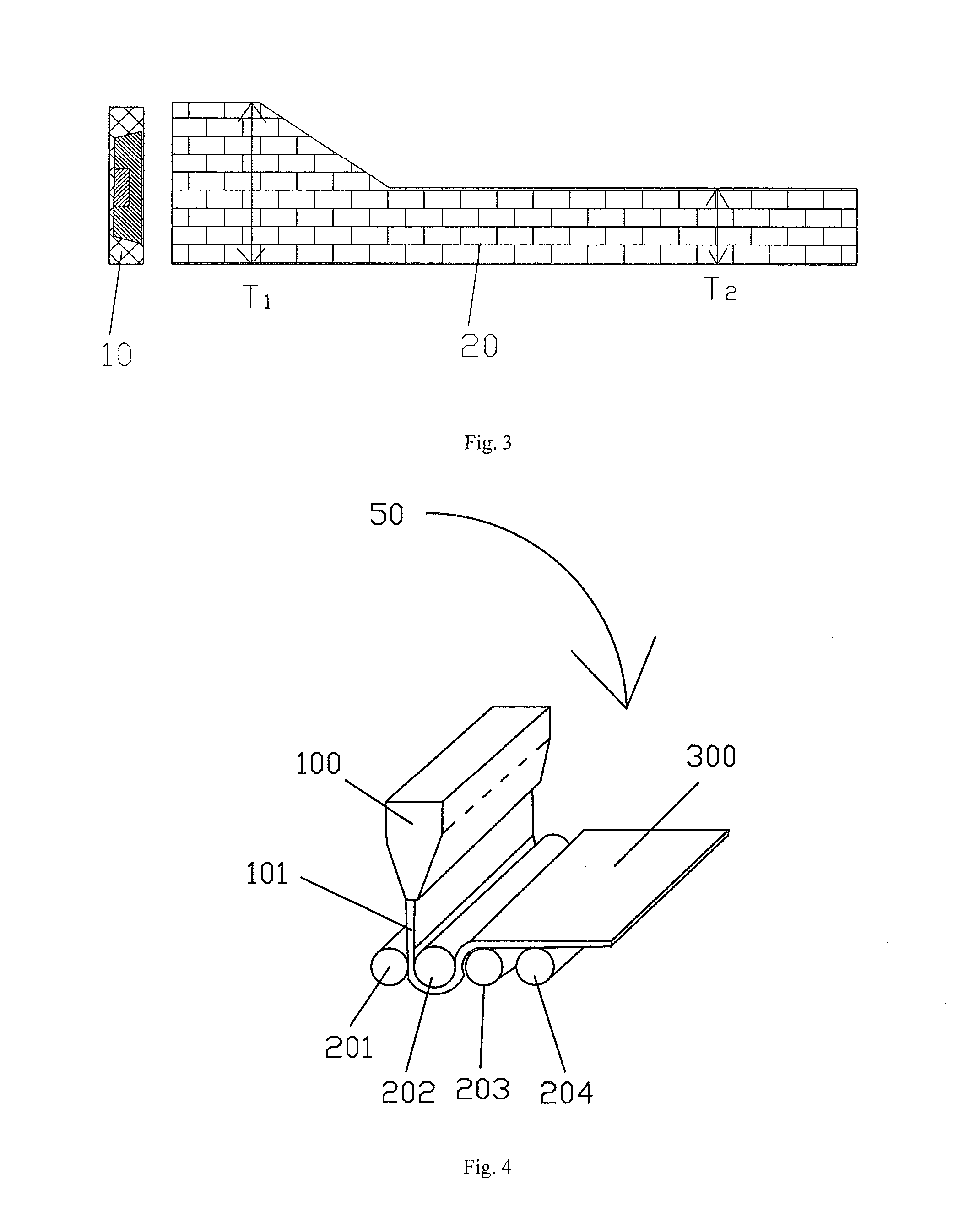
[0047]As described above, FIG. 3 shows a light guide plate 20 having a wedge-shaped projection on the light incident side thereof. The light guide plate 20 is the light guide plate to be manufactured by an apparatus according to the present disclosure. Generally speaking, the objective of the present disclosure is to manufacture a light guide plate having a varying thickness. The specific form of the light guide plate is not limited to that as shown in FIG. 3. For example, the wedge-shaped projection can be arranged on another position of the light guide plate, or the projection can have a cross section of a different shape, such as rectangle or arc.
[0048]As clearly shown in FIG. 3, a thickness T1 of a light incident side of the light guide plate 20 is larger than a thickness T2 of the rest area thereof. With such a light guide plate, not only the light coupling efficiency between a la...
PUM
| Property | Measurement | Unit |
|---|---|---|
| Thickness | aaaaa | aaaaa |
| Shape | aaaaa | aaaaa |
| Efficiency | aaaaa | aaaaa |
Abstract
Description
Claims
Application Information