Charged Particle Beam System

a particle beam and beam system technology, applied in the field of charged particle beam systems, can solve the problems of difficulty in achieving higher shutter speed, pattern tailing off and blurring, and the inability to photograph the electron diffraction pattern precisely

Inactive Publication Date: 2016-01-14
JEOL LTD
View PDF9 Cites 7 Cited by
  • Summary
  • Abstract
  • Description
  • Claims
  • Application Information

AI Technical Summary

Benefits of technology

[0020]In view of the foregoing problem, the present invention has been made. One object associated with some aspects of the present invention is to provi

Problems solved by technology

It has been difficult to achieve higher shuttering speeds.
In consequence, during photographing of the electron diffraction pattern

Method used


Image

  • Charged Particle Beam System
  • Charged Particle Beam System
  • Charged Particle Beam System

Examples


first embodiment

1. First Embodiment

1.1. Configuration of Charged Particle Beam System

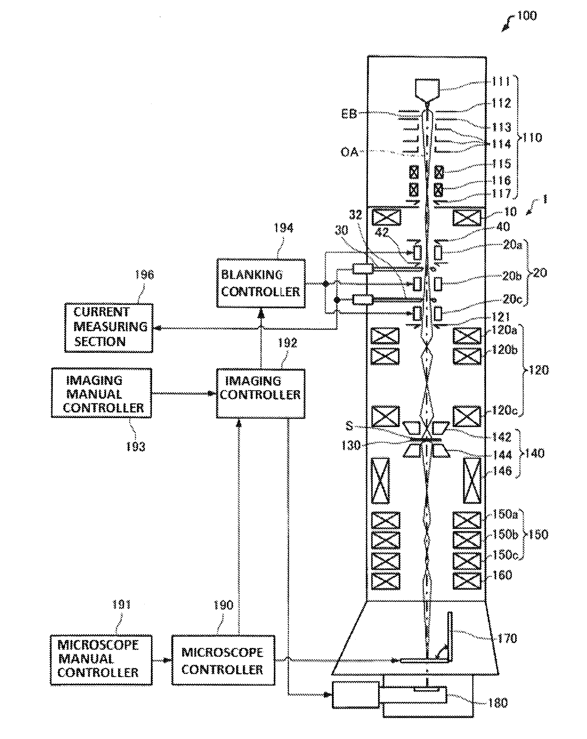
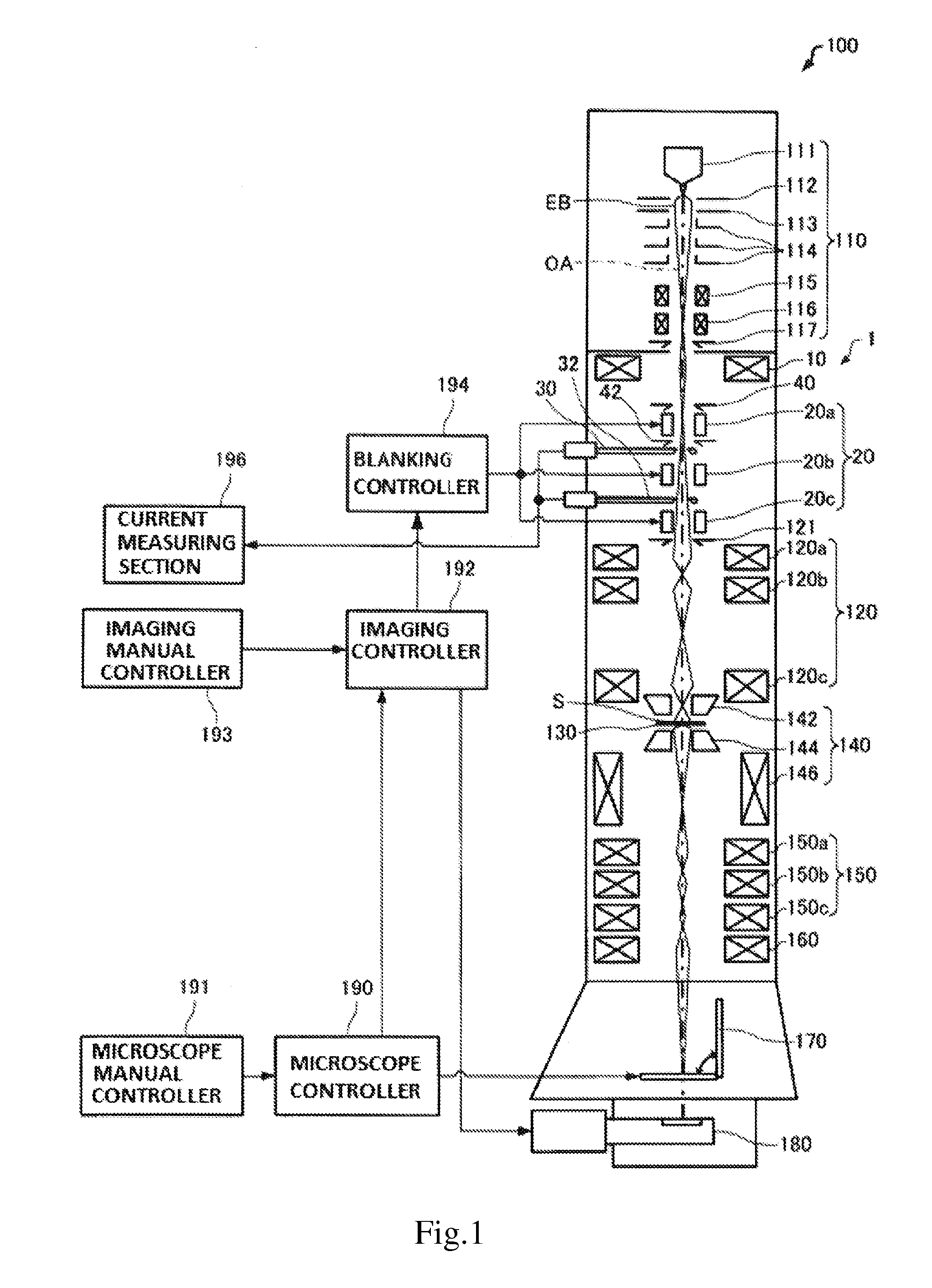
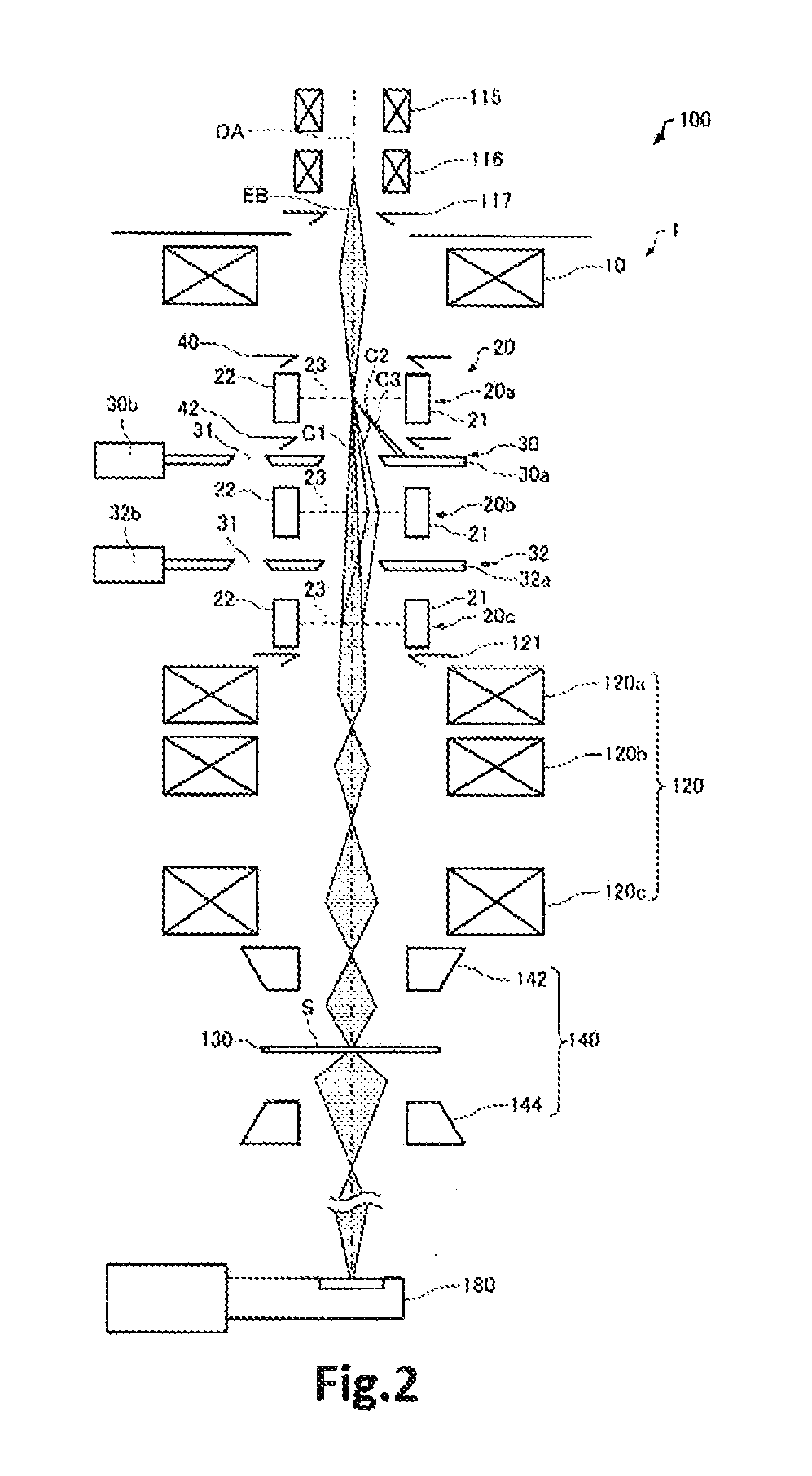
[0052]The configuration of a charged particle beam system associated with a first embodiment of the present invention is first described by referring to FIG. 1, where the system is schematically shown and generally indicated by reference numeral 100. In this example, the charged particle beam system 100 is a transmission electron microscope (TEM). A transmission electron microscope is an electron microscope for irradiating a sample S with an electron beam EB and magnifying the electron beam EB transmitted through the sample S by an imaging lens system including components 140, 150, and 160.

[0053]Referring still to FIG. 1, the charged particle beam system 100 is configured including a charged particle beam source 110, a beam blanker 1, a condenser lens system 120, a sample stage 130, the objective lens 140, the intermediate lens system 150, the projector lens 160, a fluorescent screen 170, an imager 180, a microscop...

second embodiment

2. Second Embodiment

2.1. Configuration of Charged Particle Beam System

[0133]The configuration of a charged particle beam system associated with a second embodiment of the present invention is next described by referring to FIG. 6, which schematically shows main portions of the charged particle beam system, 200, associated with the second embodiment. In FIG. 6, for the sake of convenience, only members present around the beam blanker 1 are shown. Members not shown are similar to their respective counterparts of the charged particle beam system 100 shown in FIGS. 1 and 2. Those components of the charged particle beam system 200 associated with the second embodiment which are similar in function to their respective counterparts of the charged particle beam system 100 associated with the first embodiment are indicated by the same reference numerals as in the above cited figures and a description thereof is omitted.

[0134]In the above-described charged particle beam system 100, the beam b...


PUM


Abstract

A charged particle beam system has a charged particle beam source (110) for producing a charged particle beam (EB), a beam blanker (1) and a sample stage (130) on which a sample (S) is held. The sample (S) is irradiated with the beam (EB) passed through the beam blanker (1). The beam blanker (1) has a multistage deflector assembly (20) and a first apertured portion (30). Multiple stages of deflectors (20a, 20b, 20c) for deflecting the beam (EB) are arranged in the multistage deflector assembly (20). The first apertured portion (30) is disposed between the first stage of deflector (20a) and the second stage of deflector (20b) of the deflector assembly (20). The beam (EB) which has passed through the first aperture portion (30) after being deflected by the first stage of deflector (20a) is deflected back to an optical axis (OA) by the second and subsequent stages of deflectors (20a, 20b).

Description

BACKGROUND OF THE INVENTION[0001]1. Field of the Invention[0002]The present invention relates to a charged particle beam system.[0003]2. Description of Related Art[0004]In a charged particle beam system such as a transmission electron microscope (TEM), when an electron microscope image or an electron diffraction pattern should be taken, the shutter is first activated to prevent the electron beam from hitting film or an imager such as a CCD camera. Then, the beam is made to hit the film or imager to expose it. Subsequently, the shutter is again activated such that the beam does not hit the film or imager. Consequently, the electron microscope image or electron diffraction pattern can be taken (see, for example, JPA-2006-100166).[0005]One known shutter of this type is a shutter using gun alignment coils (hereinafter may also be referred to as a gun shutter). FIG. 7 schematically shows a transmission electron microscope, 1000, that is one example of a transmission electron microscope e...

Claims


Application Information

Patent Timeline
IPC IPC(8): H01J37/04H01J37/10H01J37/26
CPCH01J37/045H01J37/26H01J2237/2802H01J2237/0435H01J37/10H01J37/28H01J2237/15
Inventor SASAKI, TAKEO
Owner JEOL LTD
Why Eureka
Try Eureka