

Oxygen carrying materials and methods for making the same
a technology of oxygen carrying materials and oxygen, which is applied in the field of oxygen carrying materials, can solve the problems of iron in the form of small particles degrading and breaking up in the reactor, the combustion of carbonaceous fuels, coal, etc., and achieves the effect of increasing strength
- Summary
- Abstract
- Description
- Claims
- Application Information
AI Technical Summary
Benefits of technology
Problems solved by technology
Method used
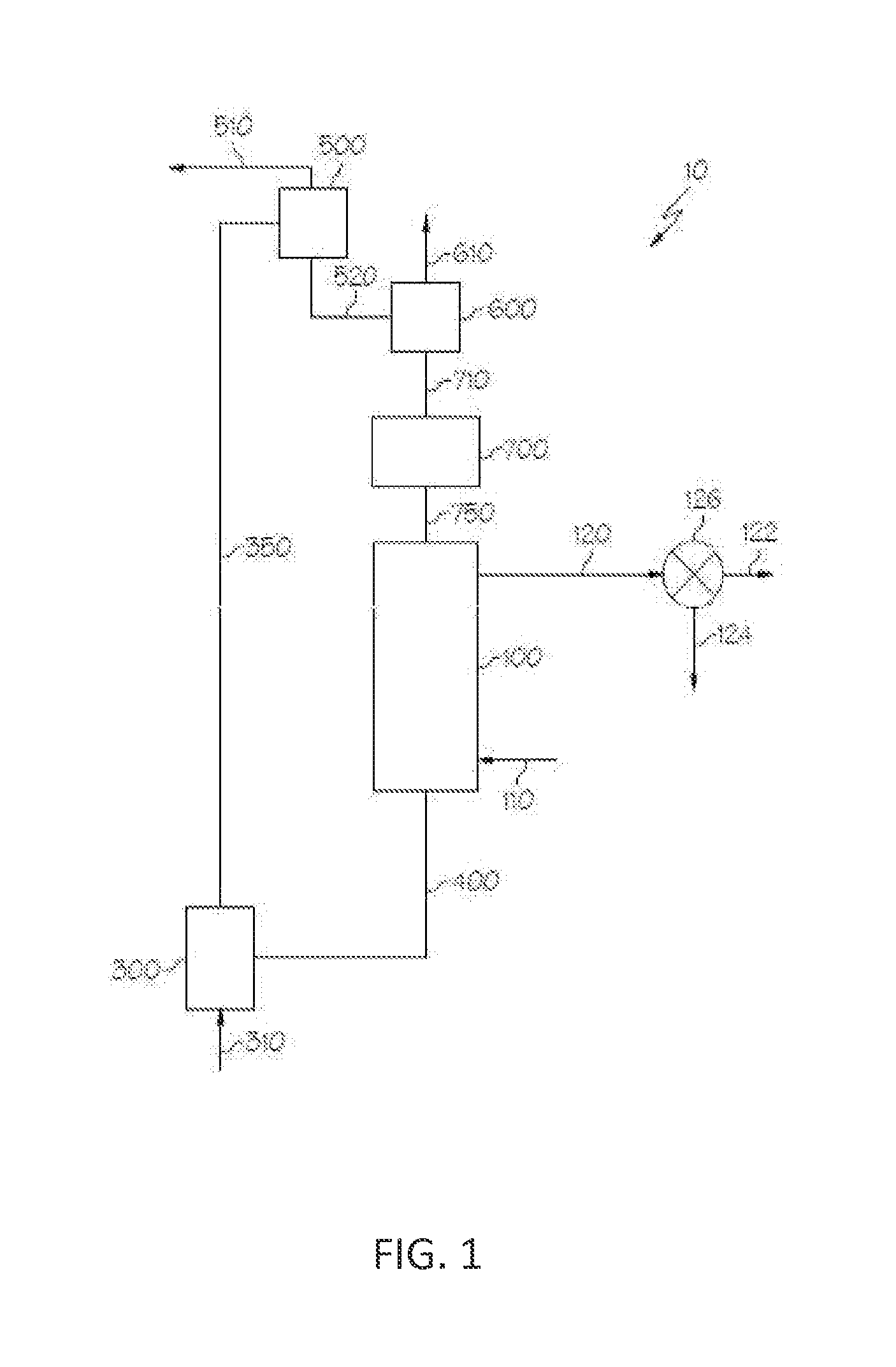
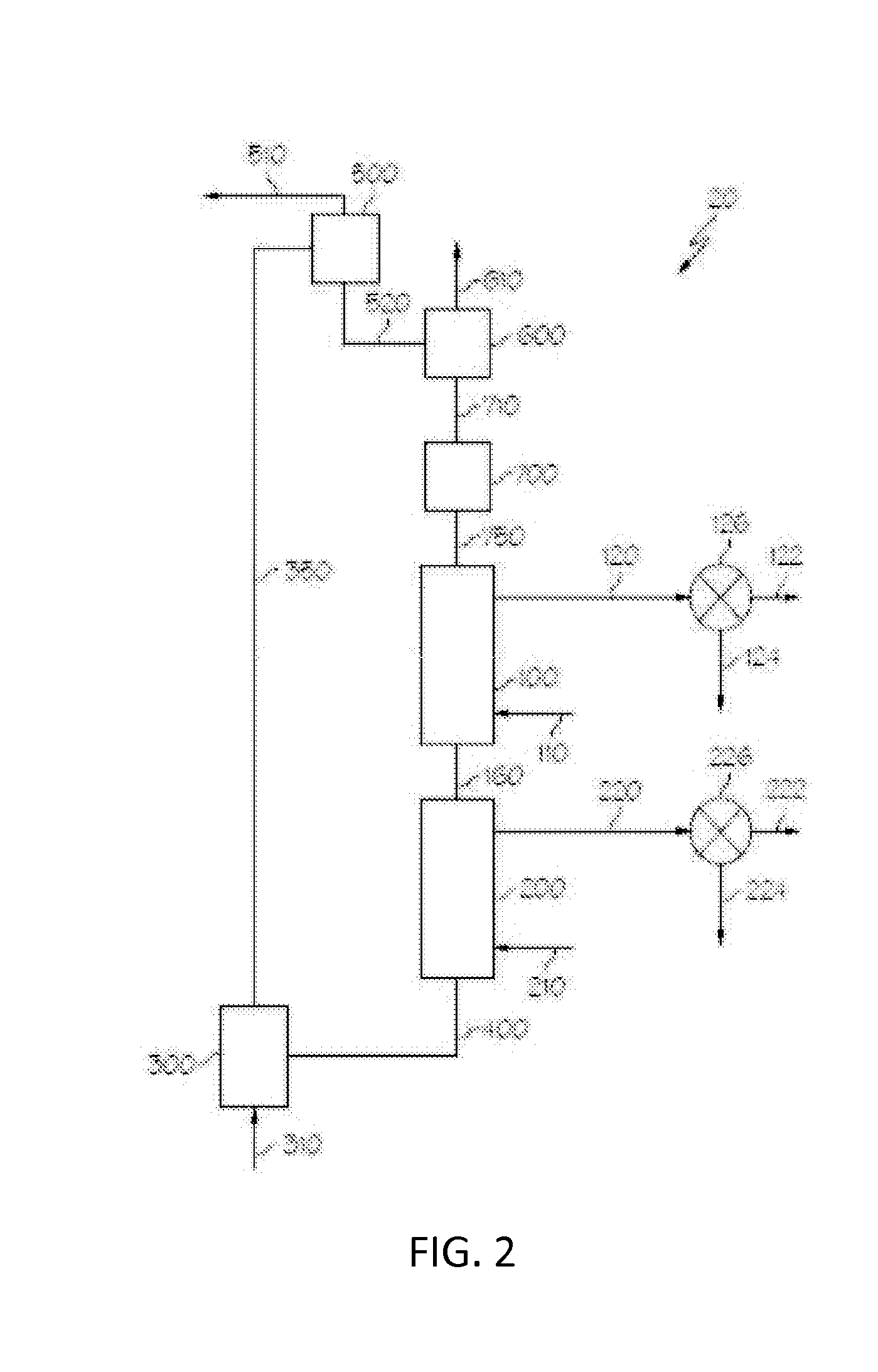
Image

Examples
example 1
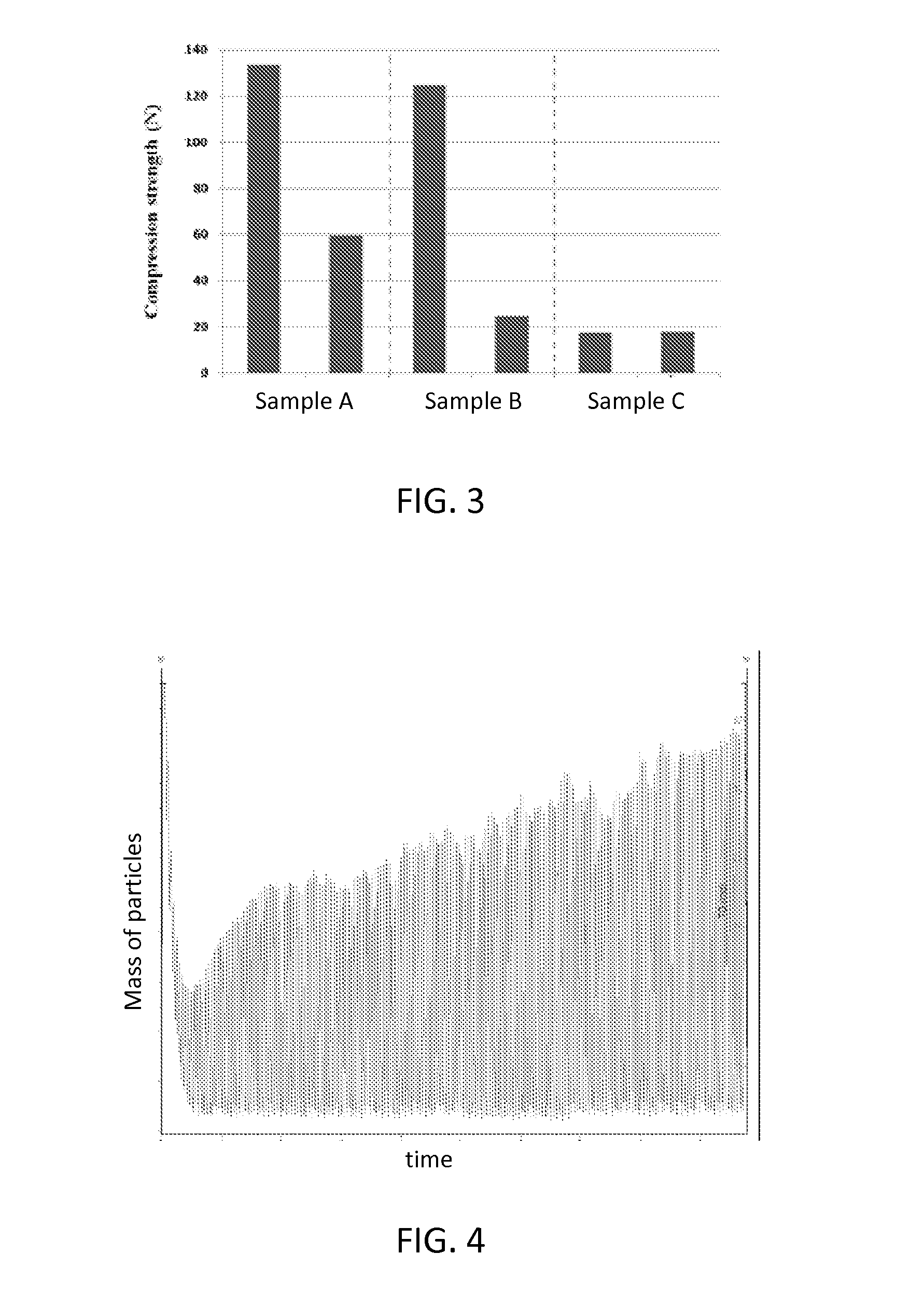
[0073]Oxygen carrying materials were prepared with varying compositions and sintered at varying times and temperatures. Component powders were well mixed with water, which was stirred to achieve a homogenous slurry mixture. The slurry was then dried at 100° C. and subsequently ground into fine powder, which was subsequently granulated into 2 mm spherical particles. The particles were then sintered. Table 1, shown below, lists several sample embodiments of oxygen carrying materials described herein, as well as some comparative examples of conventional oxygen carrying materials. Table 1 lists precursor materials by weight percentage and sintering conditions for various embodiments.
TABLE 1Sintertemper-SinterActiveInertSupportaturetimeSamplemassmaterial(s)material(s)(° C.)(hours)A50 wt %20 wt %30 wt %14002Fe2O3CalciumTiO2AluminateCompar-50 wt %none50 wt %14002ative Ex-Fe2O3TiO2ample BCompar-50 wt %20 wt %30 wt %10002ative Ex-Fe2O3CalciumTiO2ample CAluminateD20 wt %40 wt %20 wt %14003Fe2...
example 2
[0076]Calcium aluminate particles, made by mixing fine powders and water into a mixture that was granulated to 1 mm to 3 mm in size, were sintered at 900° C. and 1400° C. for two hours, respectively. FIGS. 5 and 6 show microscopic images of particles sintered at 1400° C. and FIGS. 7 and 8 show microscopic images of particles sintered at 900° C. As shown in FIGS. 7 and 8, the particles sintered at 900° C. either directly break back to fine power or easily crumble into fine powder with small amounts of applied pressure, such as the pressure from prodding tweezers. However, now referring to FIGS. 5 and 6, the 1400° C. sintered particles still maintain particle integrity and gain much higher compression strength than the un-sintered precursor particles. FIG. 6 shows the initial fine particles are sintered together to form a strong structure. FIGS. 5-8 are illustrative of the high temperature sintering necessary to densify inert refractory materials, such as calcium aluminate, that may f...
PUM
| Property | Measurement | Unit |
|---|---|---|
| temperature | aaaaa | aaaaa |
| temperature | aaaaa | aaaaa |
| temperature | aaaaa | aaaaa |
Abstract
Description
Claims
Application Information