Centrifugal pump

a centrifugal pump and centrifugal pump technology, applied in the direction of piston pumps, positive displacement liquid engines, liquid fuel engines, etc., can solve the problems of low change in cooling capacity, low circulation amount change of cooling water, and inability to generate easy change in cooling capacity

Inactive Publication Date: 2016-01-28
SAGINOMIYA SEISAKUSHO INC
View PDF19 Cites 5 Cited by
  • Summary
  • Abstract
  • Description
  • Claims
  • Application Information

AI Technical Summary

Benefits of technology

[0123]the lower main body casing which is fixed to the upper main body casing,
[0125]the blade accommodating portion, which extends horizontally from outer periphery of the lower main body casing to the inner periphery side, and
[0126]the rotor magnet accommodating portion, which is extended downwardly from the blade accommodating portion.
[0127]Therefore, in the space formed between the upper main body casing and the lower main body casing fixed to the upper main body casing,
[0128]the rotating blade member, which includes the impeller member and the rotor magnet provided under the impeller member, can be accommodated in compact.

Problems solved by technology

As a result, the circulation amount change of cooling water is low, and the change in the cooling capability is not generated easily.
However, in such a conventional centrifugal pump, it is not a strong airtight structure.
In such case, there are problems in the resisting pressure and the air-tight of the centrifugal pump.
Moreover, in the structure of a conventional centrifugal pump, the coil portion that is the motor stator cannot be detached.
Therefore, in order to use it for the centrifugal pump in which the resisting pressure and the air-tight are required, even if the casing and the piping, etc. of metallic are used, it cannot be fixed by heating such as the welding, the brazing, and the adhesion, etc.
Therefore, it is unstable, and there are problems in durability and quietness.
Moreover, in such a centrifugal pump having the conventional structure, the bearing is in the fluid, and the lubricant cannot be used.
Therefore, the axial member and the impeller member are wear-out and damaged by rotating of the impeller member.
As a result, the rattling and the decentering are caused in the impeller member.
It is difficult to keep the pump performance having the predetermined objects.

Method used


Image

  • Centrifugal pump
  • Centrifugal pump
  • Centrifugal pump

Examples


embodiment 1

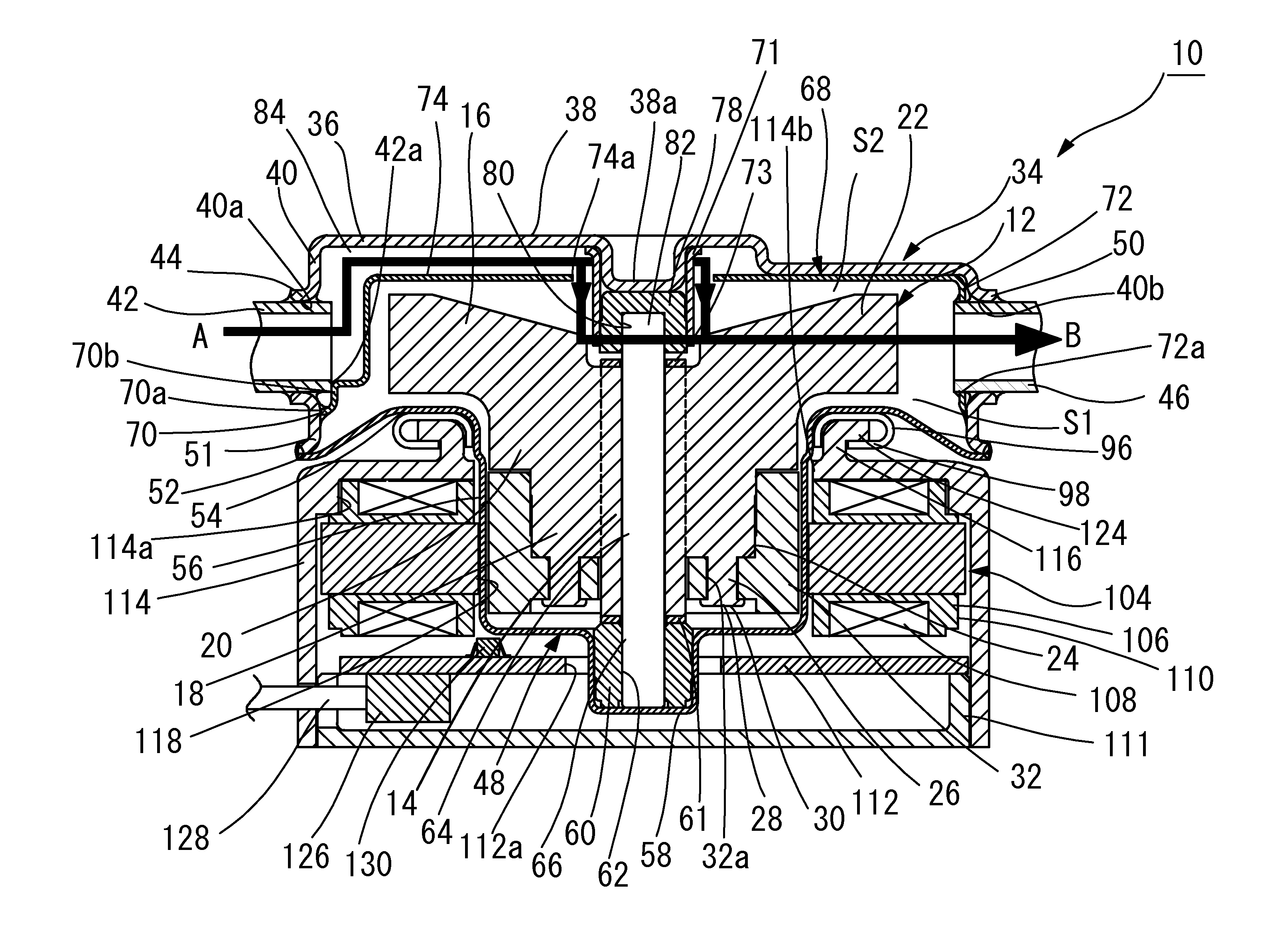
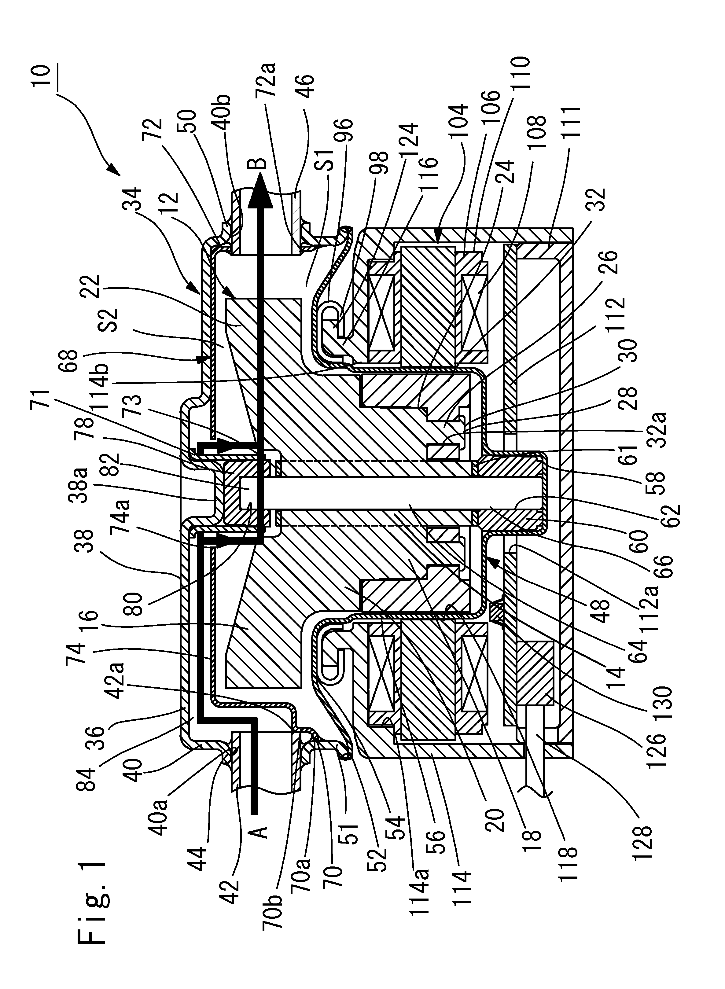
[0142]FIG. 1 is a longitudinal sectional view of an embodiment of the centrifugal pump.

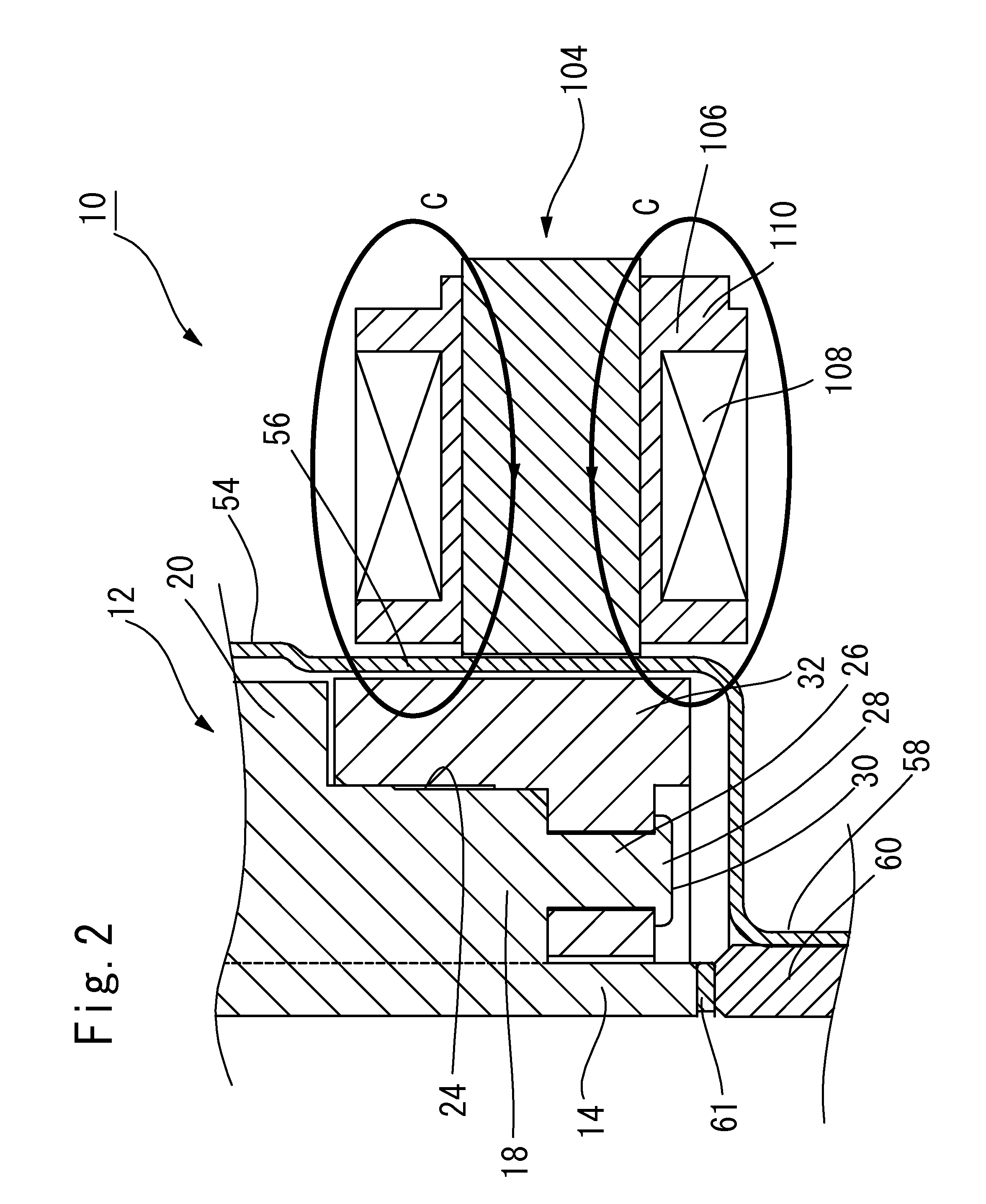
[0143]FIG. 2 is a partial enlarged sectional view of the centrifugal pump of FIG. 1.

[0144]FIG. 3 is a schematic cross-sectional view, in which disposing of the internal space S1, the fluid introducing passage 84, and the rotating accommodating space S2 of the centrifugal pump of FIG. 1.

[0145]In addition, in the specification, the wordings, such as “upper side”, “upper portion”, “upper”, “lower side”, “lower portion”, and “lower” which show vertical direction, indicate the vertical direction in each drawing.

[0146]Moreover, they indicate a relative position of each member and they do not indicate absolute position.

[0147]In FIG. 1-FIG. 2, reference numeral 10 shows exemplary centrifugal pump as a whole.

[0148]For convenience' sake of the clarification in FIG. 3, a main body casing 34, an upper main body casing 36, a lower main body casing 48, a blade casing 68, a suction side coupling member 42, and a...


PUM


Abstract

A centrifugal pump includes a rotating blade member including an impeller member and a rotor magnet provided under the impeller member, a metallic main body casing in which the rotating blade member is accommodated, and a coil portion configured to rotate the rotating blade member. The coil portion is disposed to be located in a periphery of the rotor magnet. The metallic main body casing includes an upper main body casing, and a lower main body casing which is fixed to the upper main body casing. The lower main body casing includes a blade accommodating portion, which extends horizontally from an outer periphery of the lower main body casing to an inner periphery side, and a rotor magnet accommodating portion, which extends downwardly from the blade accommodating portion.

Description

[0001]The present application claims priority to Japanese Application No. 2014-149079 filed Jul. 22, 2014 and Japanese Application No. 2015-083843 filed Apr. 16, 2015, which are both incorporated herein by reference.TECHNICAL FIELD[0002]Embodiments relate to a centrifugal pump to circulate the fluid in the closed circuit, for instance, refrigerant used for refrigerant circulation circuits such as air conditioners and freezers, and cooling water etc. used for cooling circulation circuits such as parts and apparatuses that generate heat.[0003]Moreover, this centrifugal pump is a centrifugal pump in which the resisting pressure and airtight are required.BACKGROUND ART[0004]Conventionally, as such a centrifugal pump to circulate the liquid, Patent Document 1 (JP 2003-13878, A) is open to the public.[0005]In this Patent Document 1, a centrifugal pump is disclosed, in which the structure of the impeller member is improved so that a plurality of passage portion that extends radially from t...

Claims


Application Information

Patent Timeline
Patent Type & Authority Applications(United States)
IPC IPC(8): F04D29/08F04D1/00F04D13/06F04D17/08F04D25/06F04D29/22F04D29/28F04D29/42
CPCF04D29/083F04D1/00F04D17/08F04D13/06F04D29/086F04D29/22F04D29/28F04D29/4206F04D29/426F04D25/06F04D13/0626F04D29/4266F04D29/4273
Inventor NAKAGAWA, TAIKITAKEDA, TSUYOSHI
Owner SAGINOMIYA SEISAKUSHO INC
Why Eureka
Try Eureka