Energy efficient pressure less steam generator

a technology of electrical operation and steam generator, which is applied in the direction of air humidification system, lighting and heating apparatus, heating types, etc., can solve the problems of low system efficiency, difficult portability, and bulky steam generators, and achieve high energy efficiency, easy steam generation, and low cost

Active Publication Date: 2016-01-28
VEMPATI VENKATA SUNDERESWAR RAO
View PDF29 Cites 2 Cited by
  • Summary
  • Abstract
  • Description
  • Claims
  • Application Information

AI Technical Summary

Benefits of technology

[0054]It is observed that by this invention we can generate super heated steam without any application of pressure or pressure vessels and without any heat loss to the steam during its travel to the superheating stage that too without any moving parts or accessories in the steam generator. This makes it a most convenient device, as it can be scaled up or extrapolated for higher volumes of steam, higher temperatures of steam, miniaturized models, fit to scale at any place, and offers the best solution

Problems solved by technology

Most of these steam generators are bulky, complicated, and are not easily portable due to the water reservoir, boilers and pressure vessels involved etc while the efficiency of the systems is also low as most of the stored water has to be continuously boiled or heated and kept hot throughout the evaporation process.
The surface area that can be heated is limited and the evaporation efficiency is less.
Steam generators with submerged electric resistors have draw backs of higher start up times running to about 10 minutes and have an added problem of overheating in absence of water and scaling.
Dragging of water drops is an occasional problem due to existence of boiling.
Though this device claims many improvements, it still has many limitations like submerged heating element, Limited contact area, complicated manufacturing procedure.
Though this device claims efficiency, the bulk of the water is heated and thereby reducing its efficiency.
It can be seen that the device still has to depend on heating the bulk of water first and then evapor

Method used


Image

  • Energy efficient pressure less steam generator
  • Energy efficient pressure less steam generator
  • Energy efficient pressure less steam generator

Examples


Embodiment Construction

[0066]Other features and advantages of the present invention should become apparent from the following description of the preferred process and read in conjunction with the accompanying drawings, which illustrate, by way of example, the principles of the invention.

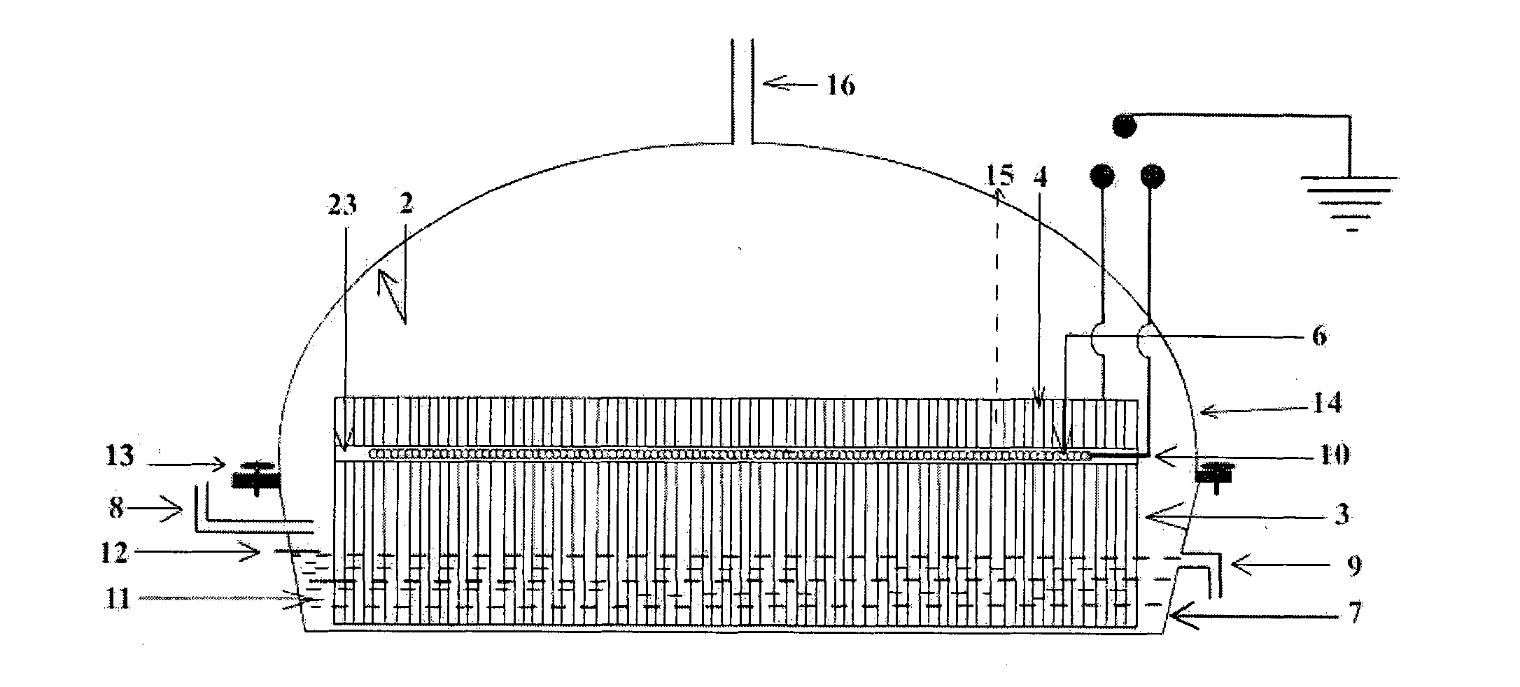
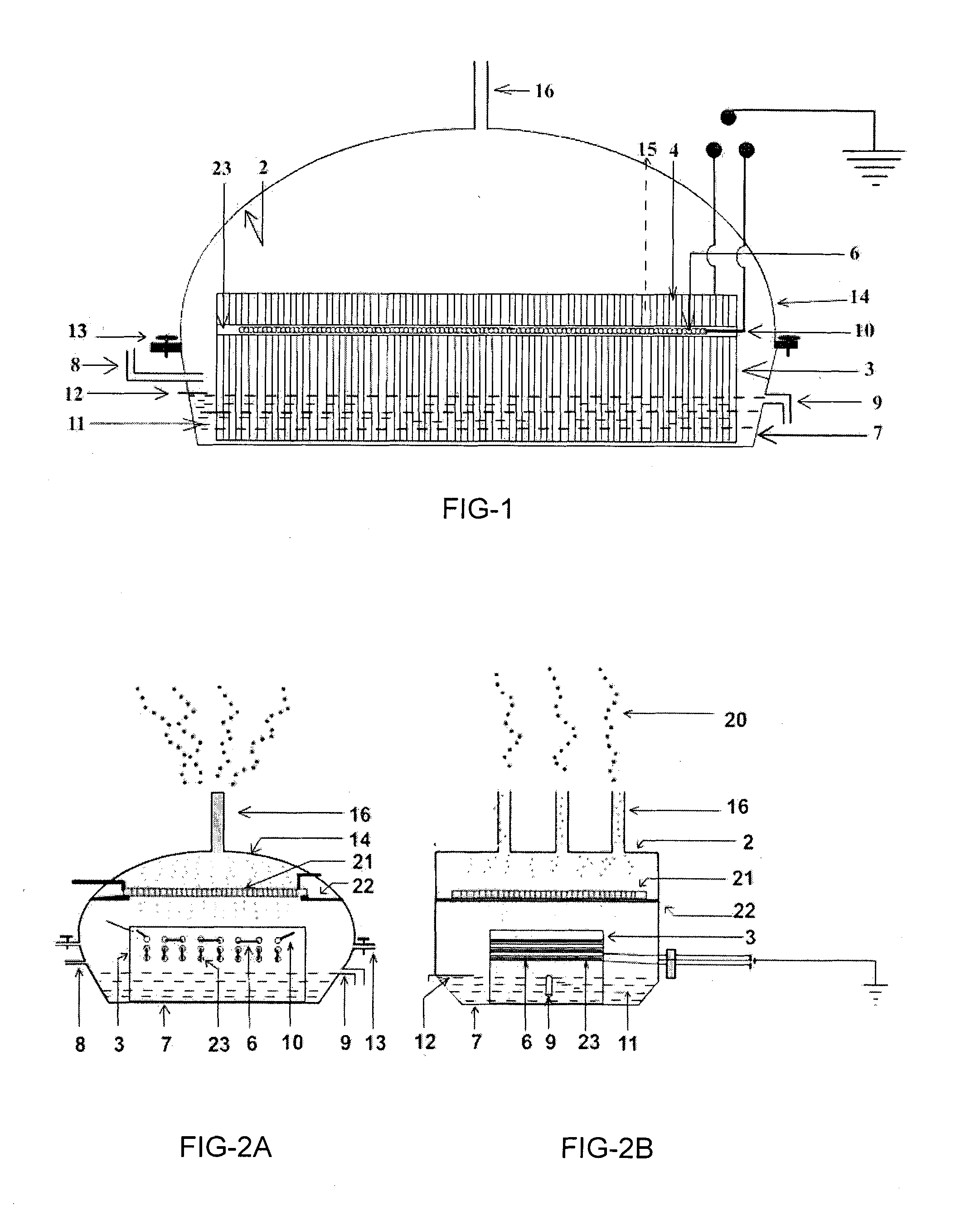
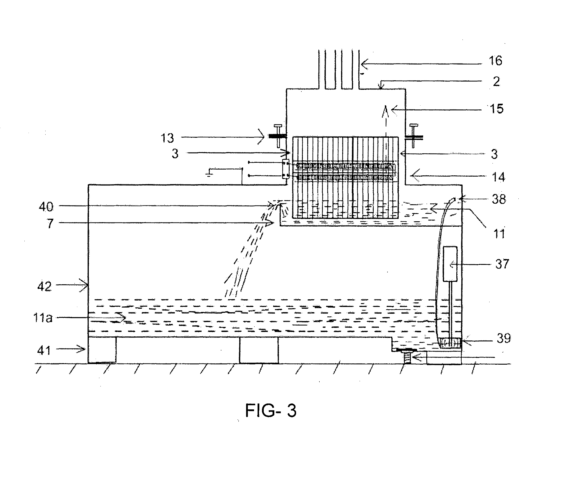
[0067]Referring to the most preferred embodiment shown in FIG. 1, the energy efficient electrically operated steam generating device (1) is having a main body (14) made from SS316 L or equivalent material, housing a porous ceramic honeycomb (3) with plurality of parallel channels (4) all vertically oriented and having electrical resistance heating element (6) installed inside the drilled holes (23) in the ceramic honeycomb (3) in such a way that the heating element(6) and the holes (23) are both mutually parallel and both are perpendicularly positioned to the axis (15) of the honeycomb channel (4). The ceramic honeycomb (3) is positioned inside the water (11) in the tray (7) and the maximum water level (12) is always maint...


PUM


Abstract

An energy efficient electrically operated steam generator is capable of producing pressure less high temperature as well as superheated steam. It comprise of main body (14) defined by side wall, roof (2) and open bottom, securely fixed to the rim of water holding tray (7). Said roof is provided with steam outlet nozzles (16) to allow the steam to emerge out of the steam generator. A porous ceramic honeycomb (3) with plurality of parallel channels (4), and grooves (5) or holes (23) are created therein for inserting heating element (6). One end of all the channels (4) is always submerged in water (11) in tray (7), and the other end of most of the channels is open to the roof and both ends of the heating element are connected to the power source for heating the water to generate steam.

Description

FIELD OF INVENTION[0001]This invention relates to an energy efficient electrically operated pressure less steam generator having a housing, with one or more heating electrodes introduced into low body density Ceramic honeycombs with their channels vertically oriented and parallel to one another with one end of all the channels resting in a tray of water with limited water level wherein water never exceeding this level such that these electrical resistance heating electrodes that are always at least 10 millimetres above the water level. More especially it is capable of producing pressure less superheated steam by introducing secondary electrical heater at a height of more than one inch over the ceramic honeycomb in such a fashion that most of the steam passes through the said secondary heater coil arrangement and thus increase the steam temperature.[0002]BACKGROUND OF THE INVENTION[0003]Many methods have been devised to generate steam and many are working even today. Most of these st...

Claims


Application Information

Patent Timeline
IPC IPC(8): F22B1/28
CPCF22B1/285F22B1/284Y02P80/15
Inventor VEMPATI, VENKATA, SUNDERESWAR, RAO
Owner VEMPATI VENKATA SUNDERESWAR RAO
Why Eureka
Try Eureka