Resonator device, electronic device, and mobile object

a technology of electronic devices and resonance devices, applied in the direction of piezoelectric/electrostrictive/magnetostrictive devices, piezoelectric/electrostriction/magnetostriction machines, impedence networks, etc., can solve the problems of large temperature difference between the temperature, piezoelectric vibration elements and the temperature detected, and achieve excellent performance

Active Publication Date: 2016-02-04
SEIKO EPSON CORP
View PDF1 Cites 14 Cited by
  • Summary
  • Abstract
  • Description
  • Claims
  • Application Information

AI Technical Summary

Benefits of technology

[0036]According to this configuration, since the mobile object having the present configuration is provided with the resonator device according to one of Application Example 9 and Application Example 10, there can be provided the mobile object provided with the advantages described in one of Application Example 9 and Application Example 10, and exerting the excellent performance.

Problems solved by technology

However, in the piezoelectric device described above, depending on the distance from the mounting terminal of the first insulating terminal to the thermo-sensitive component in the second housing section in the thickness direction, when the piezoelectric device is mounted to an external member such as an electronic apparatus, there is a possibility that the temperature difference between the temperature of the piezoelectric vibration element and the temperature detected by the thermo-sensitive component in the period when, for example, the temperature falls become large due to the adiabatic effect of the air, which is accumulated in the second housing section, and is heated in the period when the temperature rises.
As a result, there is a possibility that the frequency-temperature characteristic of the piezoelectric device described above becomes worse.

Method used


Image

  • Resonator device, electronic device, and mobile object
  • Resonator device, electronic device, and mobile object
  • Resonator device, electronic device, and mobile object

Examples


first embodiment

[0048]Firstly, a quartz crystal resonator as an example of a resonator device will be explained.

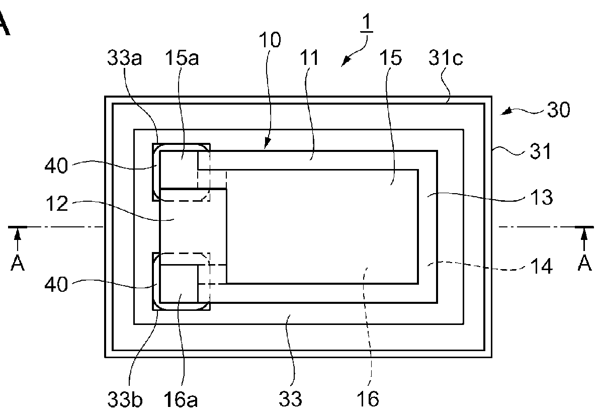
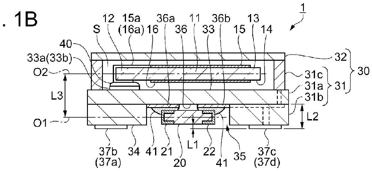
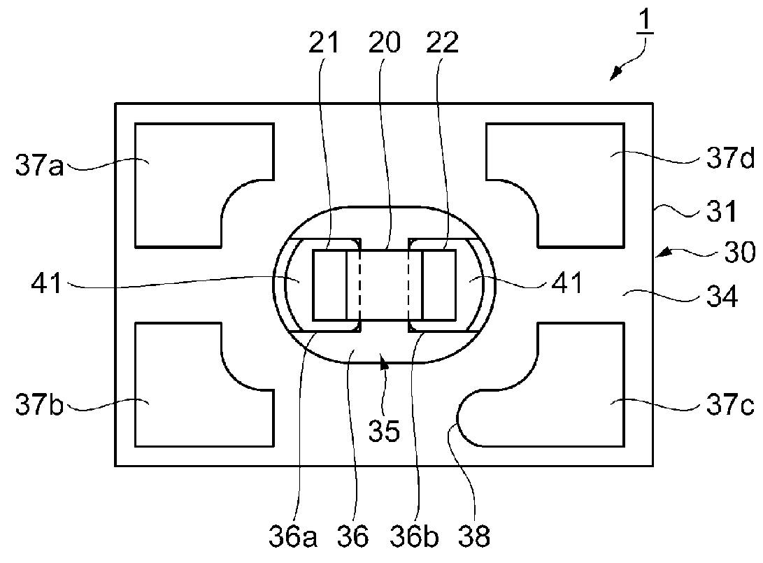
[0049]FIGS. 1A through 1C are schematic diagrams showing a general configuration of the quartz crystal resonator according to the first embodiment. FIG. 1A is a plan view viewed from the lid (a lid member) side, FIG. 1B is a cross-sectional view along the A-A line shown in FIG. 1A, and FIG. 1C is a plan view viewed from the bottom side. It should be noted that in the plan view viewed from the lid side described below including FIG. 1A, the lid is omitted. Further, the dimensional ratio of each of the constituents is different from the actual device for the sake of easier understanding.

[0050]FIG. 2 is a circuit diagram related to drive of the quartz crystal resonator including a thermo-sensitive element as an electronic element housed in the quartz crystal resonator according to the first embodiment.

[0051]As shown in FIGS. 1A through 1C, the quartz crystal resonator 1 is provided with a qu...

modified example

[0129]Then, a modified example of the first embodiment will be explained.

[0130]FIGS. 6A through 6C are cross-sectional views showing a general configuration of a quartz crystal resonator according to a modified example of the first embodiment. FIG. 6A is a plan view viewed from the lid side, FIG. 6B is a cross-sectional view along the A-A line shown in FIG. 6A, and FIG. 6C is a plan view viewed from the bottom side.

[0131]It should be noted that the parts common to the first embodiment and the modified example are denoted with the same reference numerals, and the detailed explanation thereof will be omitted, while the parts different from those of the first embodiment will mainly be explained.

[0132]As shown in FIGS. 6A through 6C, the quartz crystal resonator 2 according to the modified example is different in the arrangement direction of the thermistor 20 compared to the first embodiment.

[0133]In the quartz crystal resonator 2, the thermistor is disposed so that the longitudinal dir...

second embodiment

[0136]Next, another configuration of the quartz crystal resonator as the resonator device will be explained.

[0137]FIGS. 7A through 7C are schematic diagrams showing a general configuration of the quartz crystal resonator according to the second embodiment. FIG. 7A is a plan view viewed from the lid side, FIG. 7B is a cross-sectional view along the A-A line shown in FIG. 7A, and FIG. 7C is a plan view viewed from the bottom side.

[0138]It should be noted that the parts common to the first embodiment and the modified example are denoted with the same reference numerals, and the detailed explanation thereof will be omitted, while the parts different from those of the first embodiment will mainly be explained.

[0139]As shown in FIGS. 7A through 7C, the quartz crystal resonator 3 according to the second embodiment is different in the configuration of the package base 31 and the lid 32 compared to the first embodiment.

[0140]In the quartz crystal resonator 3, the third layer 31c of the packa...


PUM


Abstract

A quartz crystal resonator includes a quartz crystal resonator element, a thermistor, and a package base having a first principal surface and a second principal surface having an opposed surface relationship with each other, the quartz crystal resonator element is mounted on the first principal surface side, the thermistor is housed in a recessed section of the second principal surface side of the package base, a plurality of electrode terminals connected to the quartz crystal resonator element or the thermistor is disposed on the second principal surface side of the package base, and a distance in a first direction perpendicular to the first principal surface from a mounting surface of the electrode terminals to the thermistor is equal to or longer than 0.05 mm.

Description

BACKGROUND[0001]1. Technical Field[0002]The present invention relates to a resonator device, and an electronic apparatus and a mobile object each equipped with the resonator device.[0003]2. Related Art[0004]A known resonator device includes a piezoelectric device provided with a piezoelectric vibration element, a thermo-sensitive component, and a container having a first housing section for housing the piezoelectric vibration element, and a second housing section for housing the thermo-sensitive component, wherein the container is provided with a first insulating substrate having a through hole constituting the second housing section and provided with a plurality of mounting terminals disposed on a bottom section, a second insulating substrate, which is stacked on and fixed to the first insulating substrate, provided with a first electrode pad for mounting the piezoelectric vibration element disposed on the obverse surface, and provided with a second electrode pad for mounting the t...

Claims


Application Information

Patent Timeline
Patent Type & Authority Applications(United States)
IPC IPC(8): H01L41/053H01L41/047H01L41/09
CPCH01L41/053H01L41/047H01L41/09H03H9/0552H03H9/02102H03H9/1021H03H9/19H03H9/08
Inventor YAMASHITA, GO
Owner SEIKO EPSON CORP
Why Eureka
Try Eureka