Contactor, contactor assembly and control circuit

a contactor and assembly technology, applied in the direction of electromagnetic relay details, electrical apparatus, electrical relays, etc., can solve the problems of inconvenient direct monitoring of the circuit, inability to accurately detect the sensing result, and inability to weld the adhesion between the current conduction contacts of high-voltage and high-current contactors or relays. , to achieve the effect of enhancing the reliability of the contactor, simple circuit structure and accurate sensing results

Inactive Publication Date: 2016-02-11
TYCO ELECTRONICS (SHANGHAI) CO LTD
View PDF5 Cites 7 Cited by
  • Summary
  • Abstract
  • Description
  • Claims
  • Application Information

AI Technical Summary

Benefits of technology

[0072]1. The present invention senses the position of the iron core by measuring the variation in inductance by utilizing the character that the coil can generate different inductances when the iron core is in different positions in the coil, thus, the circuit structure is simple, and the sensing result is accurate.
[0073]2. The excitation signal generating circuit in the present invention outputs the excitation signal to the coil each time the working loop enters into the switched-off state, and the sensing circuit senses the position of the iron core to determine whether the contacts are adhered or not, thereby enhancing the reliability of the contactor.
[0074]3. According to the present invention, the working control circuit is arranged on the connector instead of being arranged on or in the contactor, thereby avoiding electromagnetic interference on a working circuit in the contactor, releasing the limited space of the contactor, improving the protection level of the whole contactor, reducing physical limitation

Problems solved by technology

Due to frequent connection and disconnection, welding adhesion between the current conduction contacts of a high-voltage and high-current contactor or relay may occur due to overcurrent, high-temperature electric arc destruction or aging after long-term use or other reasons.
As a result, the moving contact of the contactor or the relay is out of control and thus fails.
But for the high-voltage and high-current contactor, it is inconvenient to directly monitor the circuit.
Although these approaches are simple for customers to employ, the cost of the contactor and the maintenance cost of a product are relatively high; and furthermore, when high current flows through the relay or the conta

Method used


Image

  • Contactor, contactor assembly and control circuit
  • Contactor, contactor assembly and control circuit
  • Contactor, contactor assembly and control circuit

Examples


first embodiment

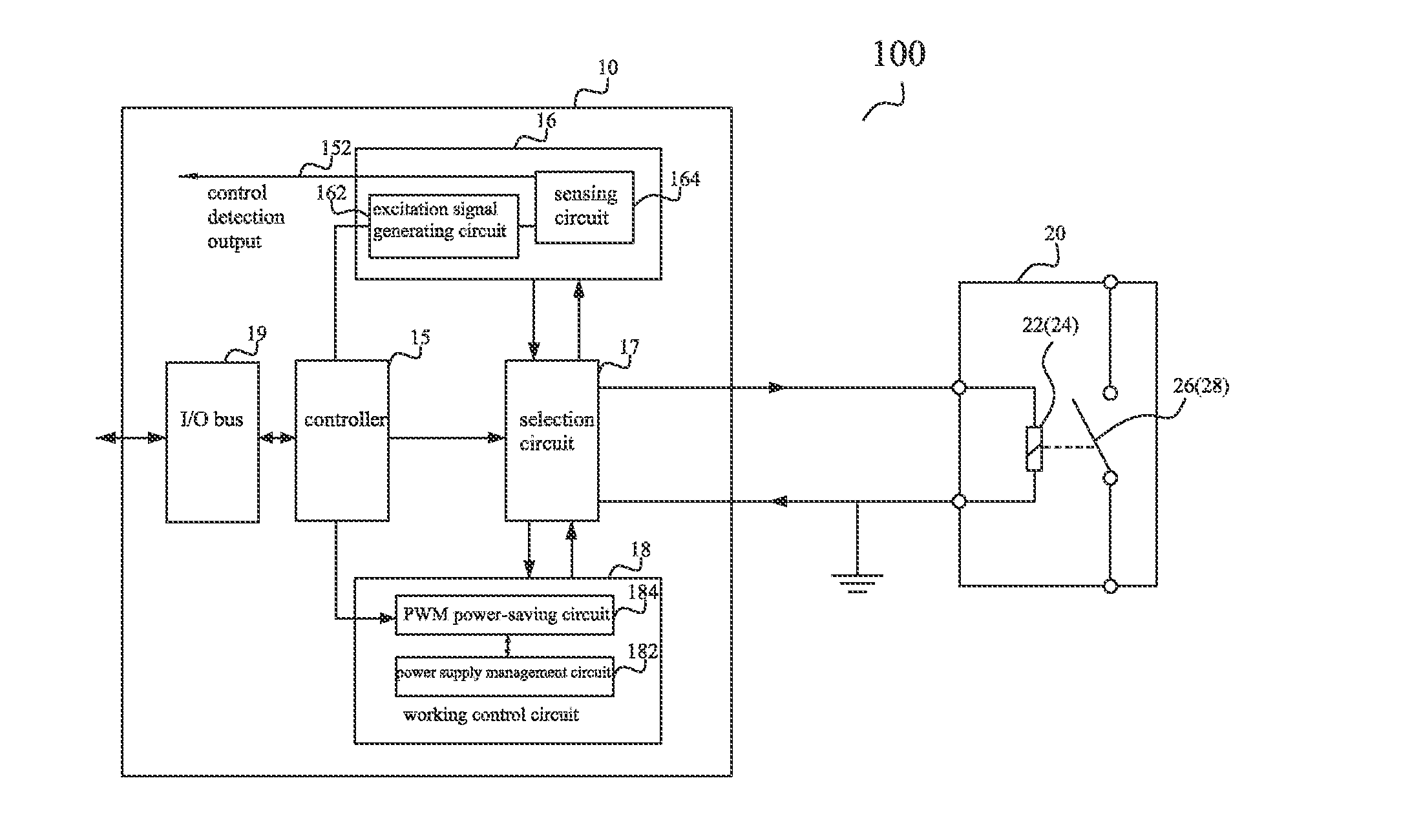
[0088]FIG. 1 is a schematic diagram of a circuit structure of a contactor 20 in the invention.

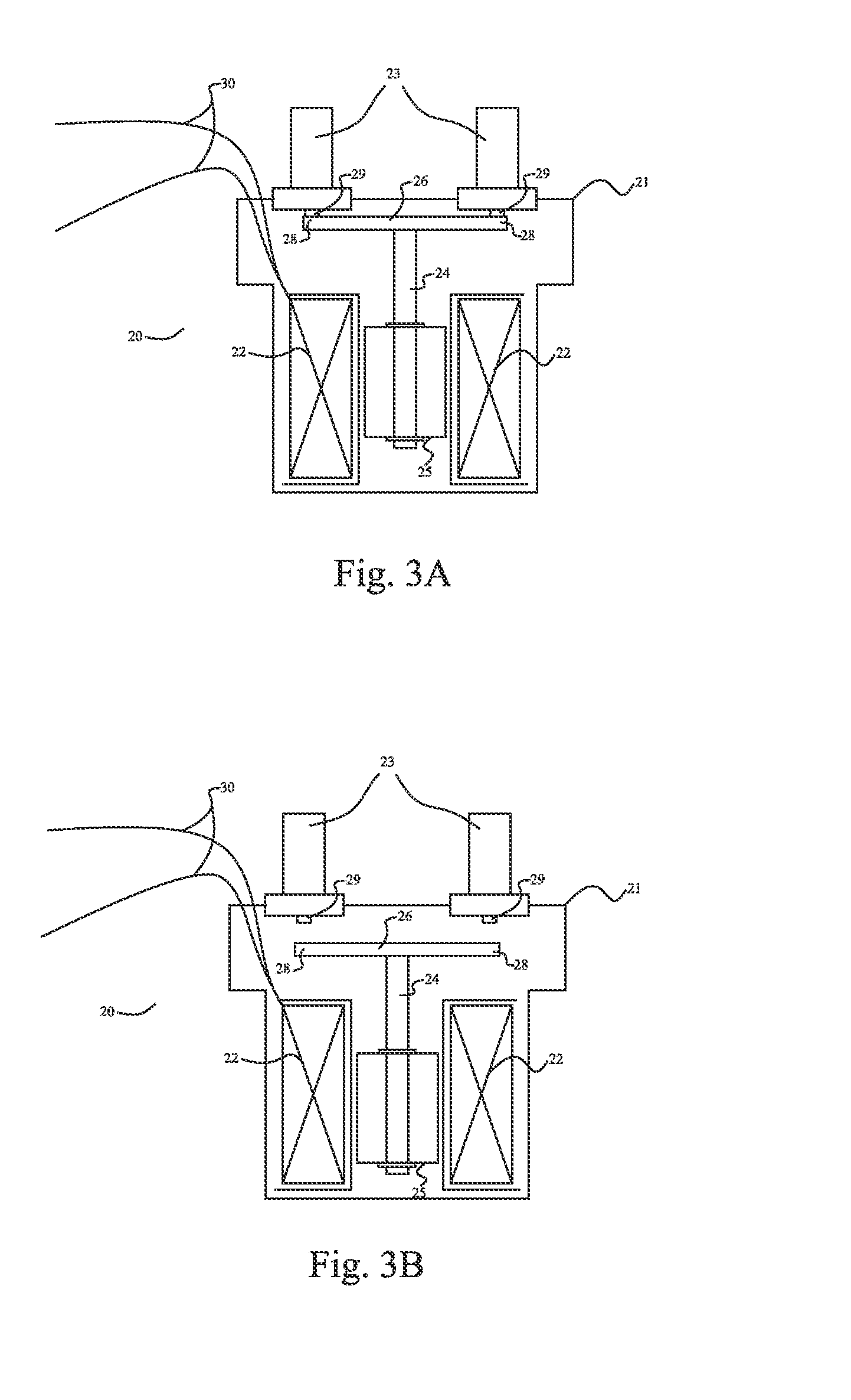
[0089]As shown in FIG. 1, a contactor (or relay) 20 comprises a control circuit 10 connected with the contactor 20. The contactor 20 has a contactor housing 21 (as shown in FIGS. 3A-3B) configured with wiring terminals 23 for connecting to a working loop. A coil 22, an iron core 24, a switch mechanism 26, moving contacts 28 and fixed contacts 29 are arranged in the housing 21. The fixed contacts 29 are connected with the wiring terminals 23 on the contactor housing 21 to form the working loop. In an embodiment of the present invention, the coil 22 is wound around the iron core 24 of the contactor 20. When the coil 22 is energized (or de-energized), magnetic force is produced (or disappears) to drive (or attract) the iron core 24 to perform reciprocating movement (when the coil 22 is de-energized, the coil 22 is driven by a releasing spring), so that the moving and the fixed contacts 28 and ...

second embodiment

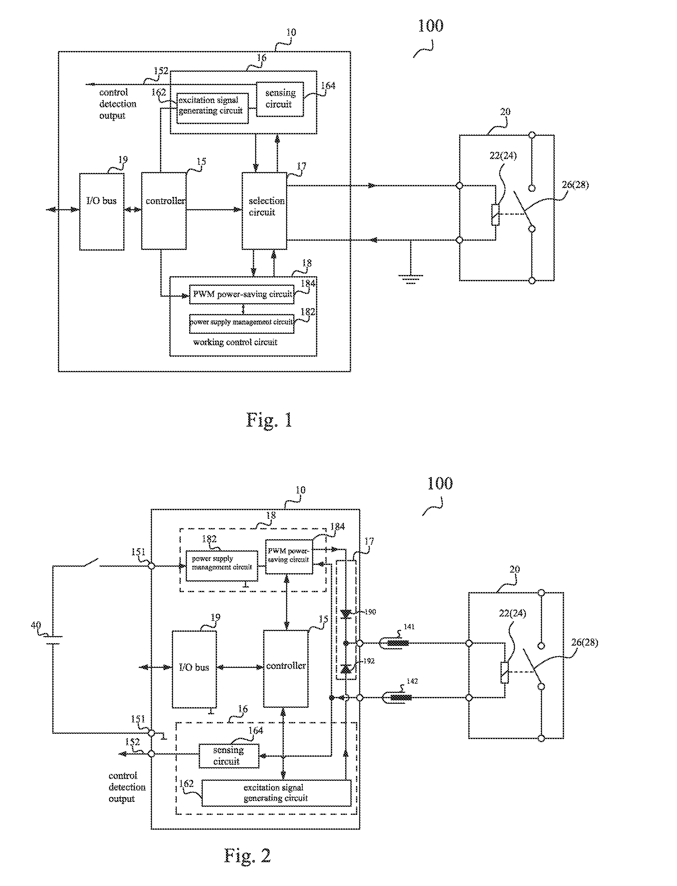
[0099]FIG. 2 is a schematic diagram of a circuit structure of a contactor 20 in the invention.

[0100]As shown in FIG. 2, the contactor (or relay) 20 comprises a control circuit 10 connected with the contactor 20. The control circuit 10 is connected with the coil 22 of the contactor 20 through plugs (141 and 142). The control circuit 10 comprises a controller 15, an iron core position sensing circuit 16, a selection circuit 17, a working control circuit 18, an I / O bus 19, a working power supply 40, etc. The contactor 20, the controller 15, the iron core position sensing circuit 16, the working control circuit 18, the I / O bus 19 and the working power supply 40 have the same structures and the functions as those in the first embodiment and will not be described herein.

[0101]The structure and the operation mode of the selection circuit 17 are different from those in the first embodiment: the structure of the selection circuit 17 is that it comprises a first diode 190 and a second diode 1...

third embodiment

[0114]FIG. 6 is a schematic diagram of a circuit structure of a contactor assembly 100 in the invention.

[0115]As shown in FIG. 6, the contactor assembly 100 comprises a contactor 20 and a connector 60 connected with the contactor 20. The contactor 20 comprises a coil 22, an iron core 24, a switch mechanism 26 and wiring terminals 23. A control circuit 10 (as shown in FIGS. 1-2) is connected with the coil 22 through leads 30. In (on or inside) the connector 60, the control circuit 10 comprises a power supply management circuit 182, a PWM power-saving circuit 184, a sensing circuit 164, an excitation signal generating circuit 162, a controller 15, an I / O bus 19, control detection output 152, etc. The control circuit 10 is detachably connected with the coil 22 of the contactor 20 through plug-in pieces 141 and 142. The control circuit 10 is arranged on a printed circuit board, and the printed circuit board is mounted on the connector 60. The connector 60 can adopt a variety of structur...


PUM


Abstract

The present invention relates to a contactor, a connector and a contactor component. According to the first aspect of the invention, a contactor relates to a switch mechanism, an iron core, an iron core position sensing circuit and a control circuit. The control circuit can measure the position of the iron core by measuring the variation in inductance by using the property that the coil can produce different inductances when the iron core is in different positions in the coil. According to the second aspect of the invention, a connector and contactor component are provided, wherein a control circuit is arranged on a connector, the control circuit comprises a PWM power-saving circuit. The PWM power-saving circuit is integrated on the connector, so that the average driving current of the contactor is reduced and meanwhile, the size of the contactor is reduced.

Description

CROSS-REFERENCE TO RELATED APPLICATIONS[0001]The application claims the benefit of Chinese Patent Application Nos. 201410381422.8 and 201410381718.X filed on Aug. 5, 2014 in China, and which disclosures are incorporated herein by reference. To the extent appropriate, a claim of priority is made to each of the above disclosed applications.FIELD OF THE INVENTION[0002]The present invention relates to a connector and a contactor assembly, and more specifically to a contactor and a connector for connecting controlling the operation of a coil in the contactor.BACKGROUND OF THE INVENTION[0003]A contactor or a relay is generally used for switching on and switching off or controlling a working circuit. For example, the contactor is provided with a coil, a moving contact and a fixed contact. When current passes through the coil in the contactor, a magnetic field can be produced to connect the moving contact and the fixed contact, thereby controlling a loaded electric appliance.[0004]Due to fr...

Claims


Application Information

Patent Timeline
IPC IPC(8): H01H50/18H01H47/22
CPCH01H50/18H01H47/22H01H3/001H01H47/002H01H47/04H01H47/325H01H50/443H01H2047/003H01H2047/008H01H50/048
Inventor ZHOU, XIAO
Owner TYCO ELECTRONICS (SHANGHAI) CO LTD
Why Eureka
Try Eureka