Information RFID tagging facilities

a technology of information rfid and tagging facilities, which is applied in the field of radio frequency identification (rfid) tags, can solve the problems of inability to interact with rfid tags, the information associated with assets, and the information left on rfid tags, and achieves the effect of increasing ionizing radiation

Active Publication Date: 2016-02-18
TEGO INC
View PDF8 Cites 67 Cited by
  • Summary
  • Abstract
  • Description
  • Claims
  • Application Information

AI Technical Summary

Benefits of technology

[0018]In embodiments, the energy to power at least one of the first RF tag and the second RF tag may be from the RF device. The first RF tag may operate using energy received from the RF device and the second RF tag may operate using energy received from an RF signal from the first RF tag. The first RF tag and the second RF tag may receive the RF signal from the RF device, such as where the data transferred from the first RF tag to the second RF tag is transferred from the first RF tag, to the RF device, and then to the second RF tag. The data transferred may be transferred directly from the first RF tag to the second RF tag without being transmitted to the RF device. The transfer of data from the first RF tag to the second RF tag may be executed without data being transmitted from the RF device to either the first RF tag or the second RF tag. The RF device may be a third RF tag powered by an external energy source, such as where the external energy source is a battery, is solar energy, and the like. The system may further comprise a third RF tag adapted to operate using energy received from an RF signal, where the third RF tag is out of range of the RF signal from the RF device, and the data transferred from the first RF tag to the second RF tag is subsequently relayed from the second RF tag to the third RF tag, such as where the third RF tag operates using energy received from an RF signal from the second RF tag. The system may further comprise a third RF tag adapted to operate using energy received from an RF signal, where the first RF tag, the second RF tag, and the third RF tag are adapted to exchange data, such as where the exchange of data is through a network protocol; the exchange of data is executed from only data transferred between the first RF tag, the second RF tag, and the third RF tag; the exchange of data comprises transfer of data between the RF device and at least one of the first RF tag, the second RF tag, and the third RF tag; and the like. In embodiments, the RF device may be a forth RF tag that is powered by an external energy source, such as where the external energy source is a battery, solar energy, and the like. In embodiments, the first RF tag and the second RF tag may be operable through effects of environmental changes due to an increase in mechanical vibration, a change in temperature, a change in humidity, an increase in ionizing radiation, due to mechanical shock, and the like.

Problems solved by technology

Conventionally, standard software, whether office, business, enterprise or of other type, is not capable of interacting with RFID tags.
RFID tags have also been traditionally limited to small amounts of data (e.g., as asset ID related information) and non-standard interface software, leaving the RFID tag, and the information associated with its asset, isolated from general access—such as through the Internet.
Many such devices lack connected power sources, and it can be quite expensive to provide batteries or energy harvesting (e.g., solar cell) technologies.

Method used


Image

  • Information RFID tagging facilities
  • Information RFID tagging facilities
  • Information RFID tagging facilities

Examples


Embodiment Construction

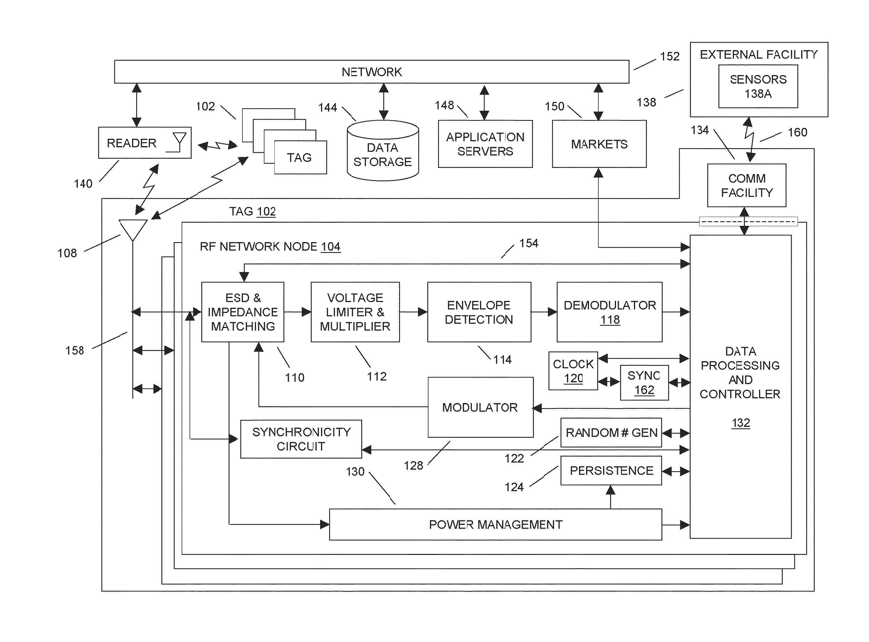
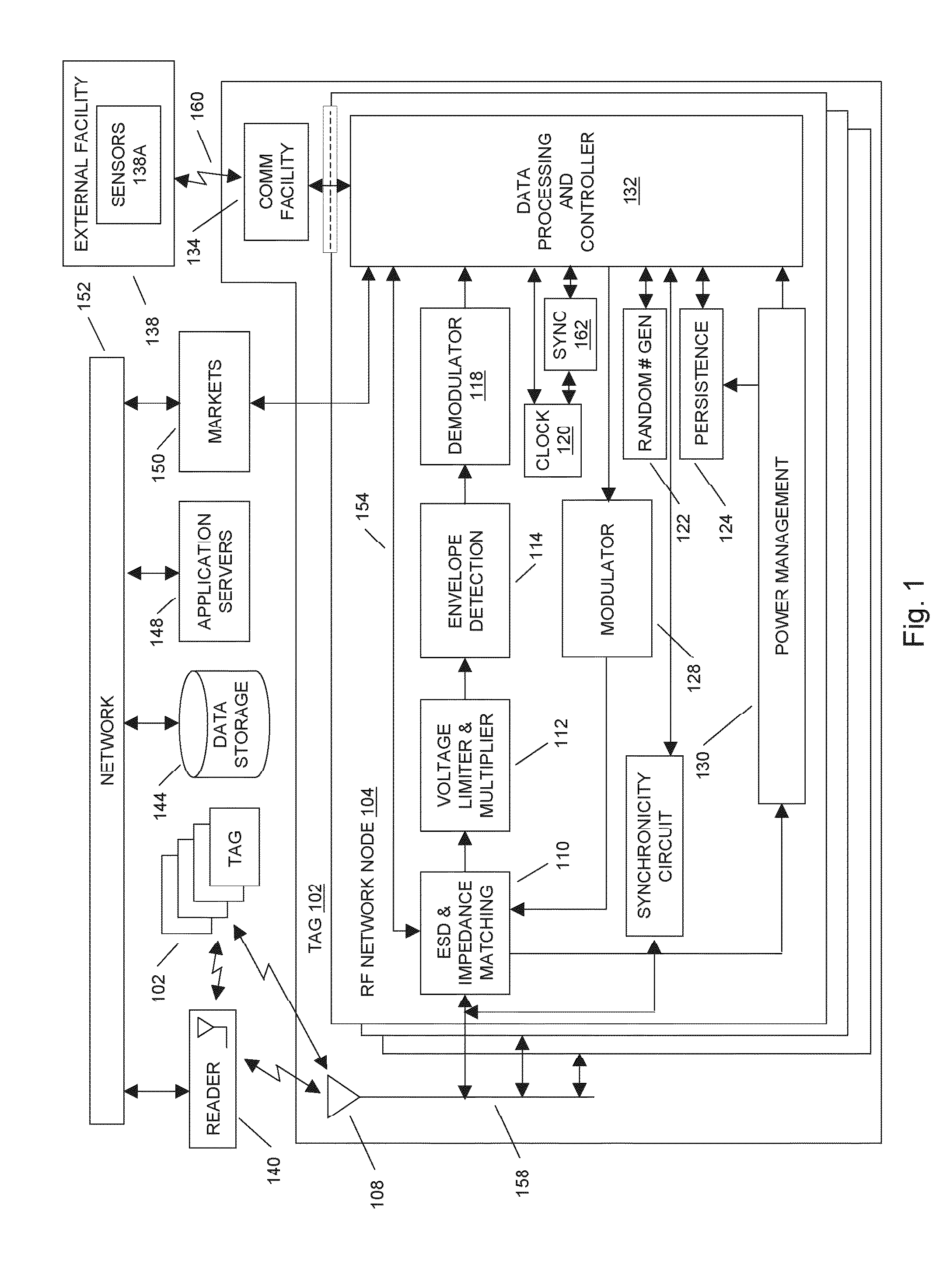
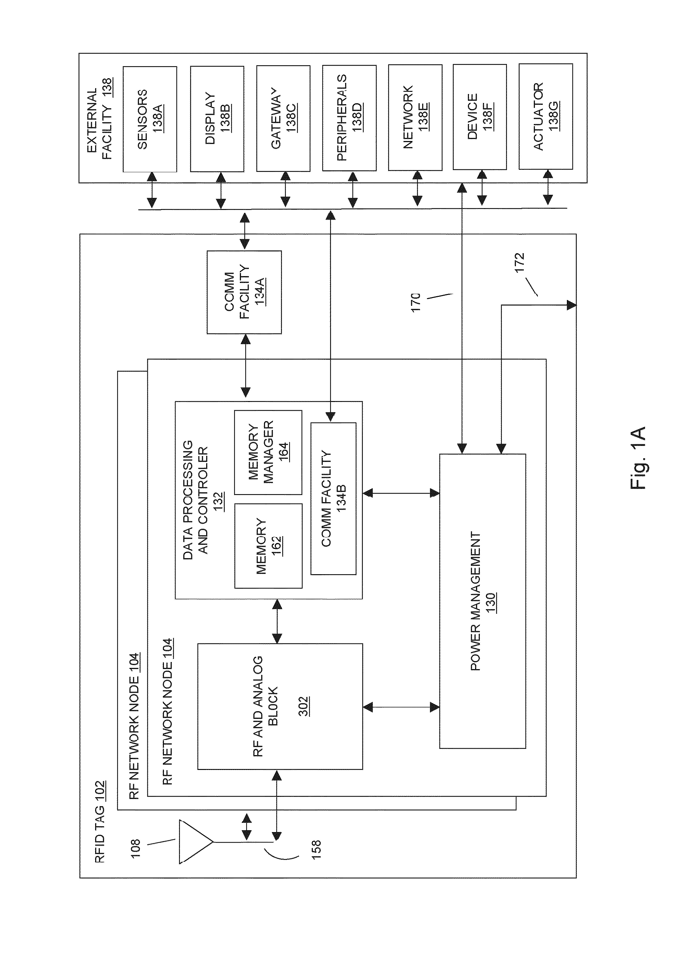
[0064]In aspects of the systems and methods described herein, although the term radio frequency identification (RFID) tag is used throughout the disclosure, the usage of this term is not meant to be limiting, such as to traditional RFID technologies (e.g., RFID technologies utilizing RFID protocols for interfacing with RFID tags, such as containing an identifier code for inventory tracking, and the like). The usage of the term RFID tag in the present disclosure pertains more generally to electronic devices communicating at least in part through wireless RF technology, including any near-field and / or far-field technologies and communication protocols known to the art.

[0065]In aspects of the systems and methods described herein, a radio frequency identification (RFID) tag may use multiple RF network nodes (e.g. radio microchips) to communicate information to a RFID reader, a network, other RFID network nodes, or the like. The communication of the information may be provided to the RFI...


PUM


Abstract

In embodiments of the present invention improved capabilities are described for a system of information RFID tagging facilities comprising a first radio frequency (RF) tag and a second RF tag, wherein the first RF tag and the second RF tag are adapted to operate using energy received from an RF signal, wherein: (i) at least one of the first RF tag and the second RF tag receives an RF signal from an RF device, (ii) the first RF tag transmits data to the second RF tag, and (iii) the second RF tag stores the transmitted data from the first RF tag in a memory on the second RF tag.

Description

CROSS-REFERENCE TO RELATED APPLICATIONS[0001]This patent application is a continuation-in-part of U.S. patent application Ser. No. 14 / 599,070 filed Jan. 16, 2015 (TEGO-0016-U01), which is incorporated by reference in its entirety. This patent application claims the benefit of the following provisional patent applications, which are hereby incorporated by reference in their entirety: U.S. patent application 62 / 057,277 filed Sep. 30, 2014 (TEGO-0014-P01) and U.S. patent application 62 / 063,588 filed Oct. 14, 2014 (TEGO-0015-P01).[0002]U.S. patent application Ser. No. 14 / 599,070 is a continuation-in-part of U.S. patent application Ser. No. 13 / 671,323, filed Nov. 7, 2012 (TEGO-0012-U01), now U.S. Pat. No. 8,988,223, which is incorporated by reference in its entirety, and which claims the benefit of the following provisional patent application, which is hereby incorporated by reference in its entirety: U.S. patent application 61 / 556,359, filed on Nov. 7, 2011 (TEGO-0011-P01).[0003]U.S. pa...

Claims


Application Information

Patent Timeline
Patent Type & Authority Applications(United States)
IPC IPC(8): G06K7/10
CPCG06K7/10009H04L67/1097G06K7/0008G06K19/0723G06K19/07309H04L67/04H04L67/12H01Q1/2225H01Q1/38H01Q9/285Y04S40/18G06K7/10158
Inventor BUTLER, TIMOTHY P.MATS, LEONIDPULESTON, DAVID
Owner TEGO INC
Why Eureka
Try Eureka