
Heat-conductive silicone composition

a silicone composition and heat-conductive technology, applied in the direction of heat-exchange elements, chemistry apparatuses and processes, etc., can solve the problems of heat conductivity, lowering performance, and uneven thermal conduction, and achieve sufficient heat-dissipation performance and sufficient spread

Active Publication Date: 2016-03-03
SHIN ETSU CHEM IND CO LTD
View PDF4 Cites 10 Cited by
  • Summary
  • Abstract
  • Description
  • Claims
  • Application Information

AI Technical Summary

Benefits of technology

The silicone composition in this patent allows for the heat-dissipating grease to be compressed and spread out over the whole heat-generating part after being subjected to high temperatures during a reflow process. This results in effective heat-dissipating performance.

Problems solved by technology

It is widely known that electronic parts such as semiconductor packages generate heat in use, thereby lowering the performance thereof.
In this case, if there is a space between the heat-generating member and the cooling member, thermal conduction does not proceed smoothly because of the presence of air, which is poor in heat conductivity, and therefore, the temperature of the heat-generating member cannot be sufficiently reduced.
However, the reflow process of subjecting to high temperature of 200° C. or higher extremely accelerates curing of the thermosetting heat-dissipating grease.
Therefore, the heat-dissipating grease cannot be compressed into a prescribed thickness, and the applied heat-dissipating grease cannot sufficiently spread over the whole heat-generating part.
Thus, there is a problem of insufficient heat-dissipating performance.

Method used


Image

  • Heat-conductive silicone composition
  • Heat-conductive silicone composition
  • Heat-conductive silicone composition

Examples


examples

[0069]Hereinafter, the present invention will be more specifically described with reference to examples and comparative examples, but the present invention is not limited to the following examples. Tests relating to the effects of the present invention were performed in the manner described below.

[Storage Elastic Modulus]

[0070]The silicone composition was applied between two parallel plates each having a diameter of 2.5 cm so as to give a thickness of 2 mm. Then, a program was constructed for heating the coated plates from 25° C. to 125° C. at a temperature increase rate of 10° C. / min, from 125° C. to 145° C. at a temperature increase rate of 2° C. / min, and from 145° C. to 150° C. at a temperature increase rate of 0.5° C. / min and then holding them at 150° C. for 7,200 seconds; and storage elastic modulus after 3,600 seconds and 7,200 seconds from the start of holding at 150° C. were measured. The measurement was performed using a viscoelasticity measurement apparatus (Type: RDAIII, ...

examples 1 to 13

[0087]

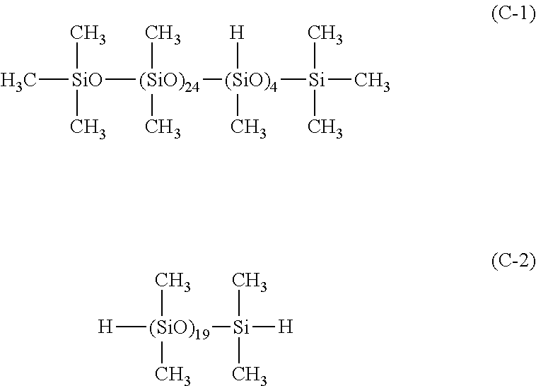
TABLE 11234567CompositionA-1100100100100100100(parts by mass)A-2100B-1490490654368490490490B-2324324432244324324324B-310010013476100100100Total amount of9149141220688914914914fillerC-17.97.77.97.93.29.511.9C-26.9D-10.060.060.060.060.060.060.06E-1100100100100100100100F-10.40.40.40.40.40.40.4SiH / SiVi1.01.01.01.01.01.21.5(number ratio)Storage elastic14650931019690109201495053060180080modulus(after 3,600 sec)Storage elastic5556046320704403250028810183110486640modulus(after 7,200 sec)after 3,600 sec / 0.260.200.280.340.520.290.37after 7,200 secViscosity9.59.1245.29.39.18.8(Pa · S)Heat2.12.02.71.22.12.01.9conductivity(W / m ·° C.)EvaluationThickness of34364834463943resultsiliconecompositionaftercrushabilitytest (μm)Result of0.880.870.660.910.710.800.72spreadabilitytest(area coveredwith siliconecomposition / areaof siliconwafer)8910111213CompositionA-1100100100100100100(parts by mass)A-2B-1490490490490490490B-2324324324324324324B-3100100100100100100Total amount of914914914914914914fillerC-...


PUM

PropertyMeasurementUnit
kinematic viscosityaaaaaaaaaa
temperatureaaaaaaaaaa

Abstract

A silicone composition that contains (A) an organopolysiloxane having at least two aliphatic unsaturated hydrocarbon groups per molecule, (B) a filler containing an aluminum powder and a zinc oxide powder, (C) an organohydrogenpolysiloxane having two or more silicon-bonded hydrogen atoms per molecule, and (D) a platinum group metal catalyst, in which a cured product of the silicone composition exhibits a ratio of a storage elastic modulus after 3,600 seconds from the start of measurement to a storage elastic modulus after 7,200 seconds from the start of measurement of 0.7 or less, the storage elastic modulus G′ being measured by constructing a program for holding a sample at 150° C. for 7,200 seconds after the sample is heated from 25° C. to 125° C. at a temperature increase rate of 10° C. / min, from 125° C. to 145° C. at a temperature increase rate of 2° C. / min, and from 145° C. to 150° C. at a temperature increase rate of 0.5° C. / min.

Description

TECHNICAL FIELD[0001]The present invention relates to a heat-conductive silicone composition.BACKGROUND ART[0002]It is widely known that electronic parts such as semiconductor packages generate heat in use, thereby lowering the performance thereof. To solve this problem, various heat dissipating techniques have been used. One typical method is to provide a cooling member such as a heat spreader in the vicinity of a heat-generating part and bring them into close contact to effectively remove heat through the cooling member.[0003]In this case, if there is a space between the heat-generating member and the cooling member, thermal conduction does not proceed smoothly because of the presence of air, which is poor in heat conductivity, and therefore, the temperature of the heat-generating member cannot be sufficiently reduced. To prevent such phenomena, there have been conventionally used, for the purpose of preventing the presence of air, heat-dissipating greases or heat-dissipating shee...

Claims


Application Information

Patent Timeline
Patent Type & Authority Applications(United States)
IPC IPC(8): C08L83/04C09K5/08
CPCC08L83/04C08L2205/035C08L2205/025C09K5/08C08G77/12C08G77/20C08L2205/02C08K2003/2296C08K2003/0893C08K5/56C08K2003/0812C08L83/00C08K3/08C08K3/22
Inventor KITAZAWA, KEITAYAMADA, KUNIHIRO
Owner SHIN ETSU CHEM IND CO LTD
Learn More