Suspension rotary water pressure energy conversion power output device
a technology of energy conversion power output and rotary water pressure, which is applied in the direction of machines/engines, fluid couplings, couplings, etc., can solve the problems of low controllability, low power generation efficiency, and high installation cost, and achieves high efficiency power output, simple structure, and easy operation.
- Summary
- Abstract
- Description
- Claims
- Application Information
AI Technical Summary
Benefits of technology
Problems solved by technology
Method used
Image
Examples
embodiment 1
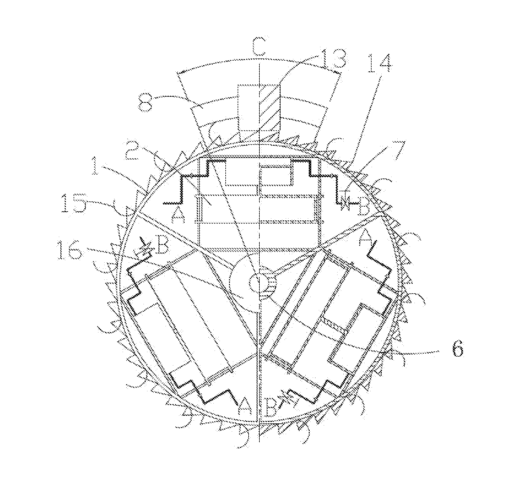
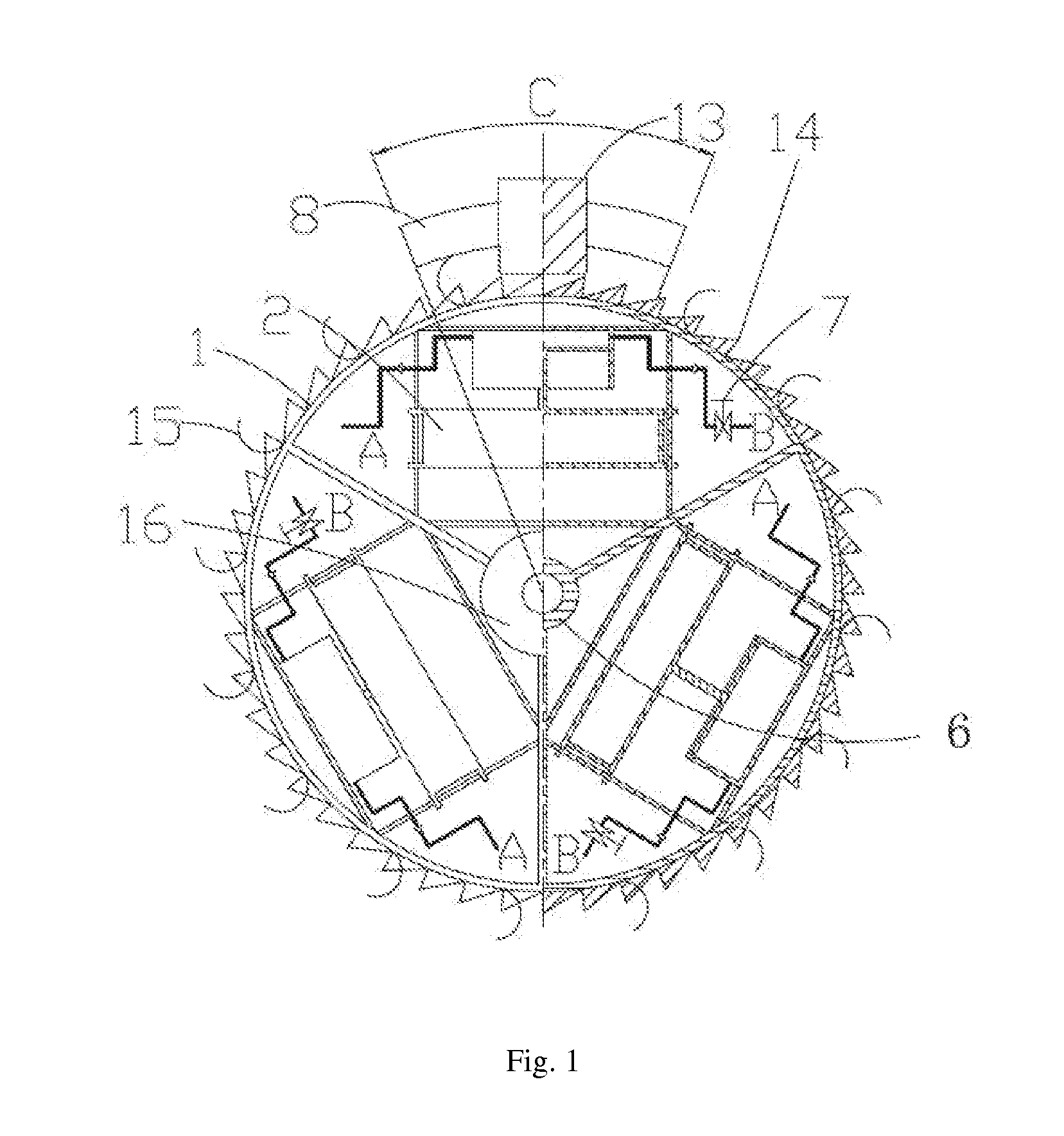
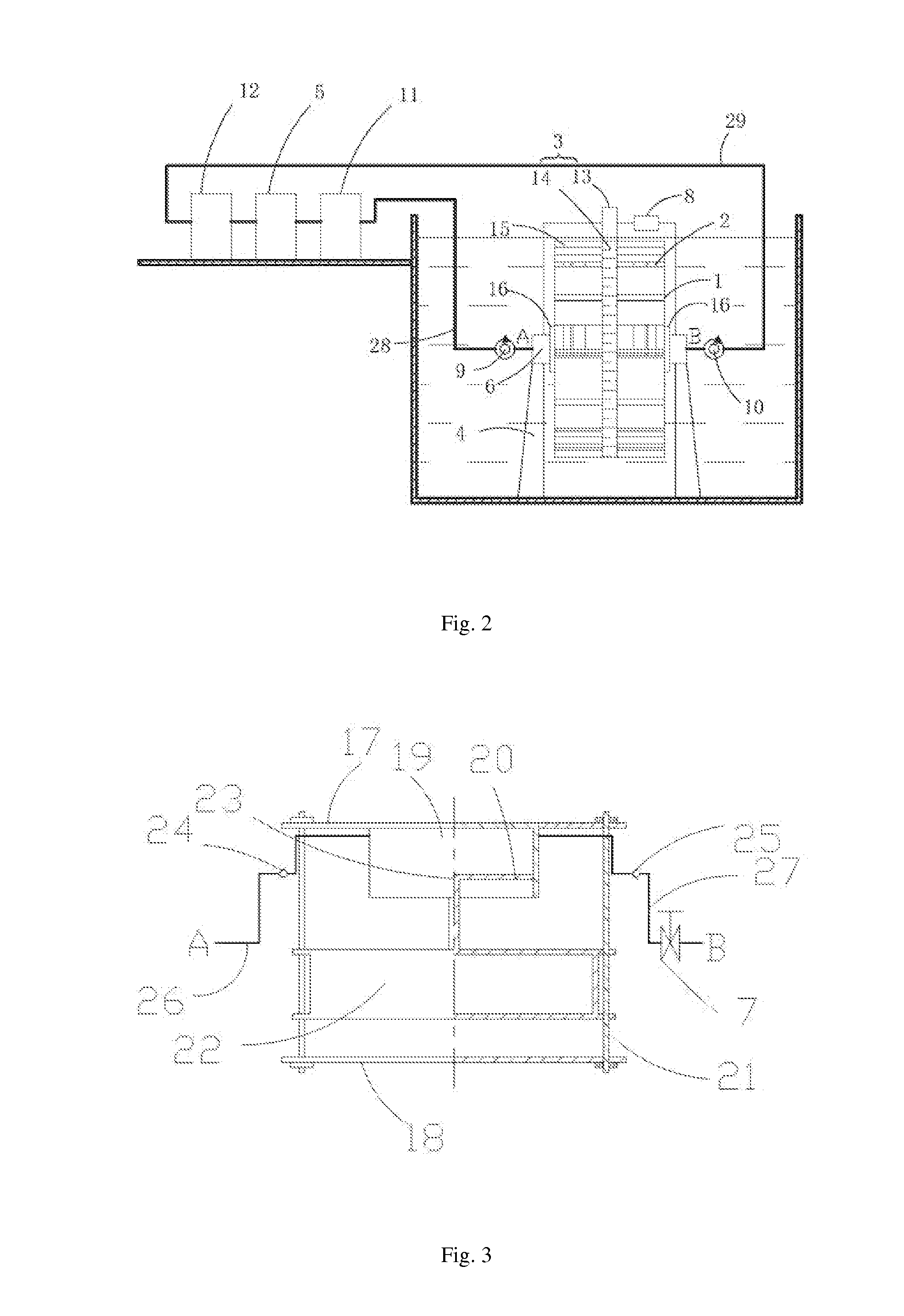
[0016]The device of the present invention includes energy converters 2 fixedly connected with a rotating shaft 6, a ring-shaped frame 1 coaxial and fixedly connected with the rotating shaft 6, a turnover mechanism 3, a supporting base 4, and a hydraulic transmission mechanism. The transmission mechanism includes a hydraulic cylinder 19, one-way valves 24, 25, oil pipes 26, 27, a hydraulic oil tank 11, a high-pressure oil accumulator 12 and a hydraulic actuator 5.
[0017]The energy converter 2 includes a floating buoy 22, upper and lower base plates 17, 18, the hydraulic cylinder 19, and a piston 20. The upper and lower base plates 17, 18 are fixedly connected together by at least two fixation rods 21. The hydraulic cylinder 19 is mounted on the upper base plate 17. An upper end of the floating buoy 22 is provided with a connecting rod 23, which is connected with the piston 20 of the hydraulic cylinder 19. The floating buoy 22 and the fixation rods 21 are movably connected by linear be...
embodiment 2
[0024]The structure of the energy converter in embodiment 2 is different from that of embodiment 1. The energy converter 2 includes a floating buoy 38, upper and lower base plates 31, 32, two opposite hydraulic cylinders 33, 34 with pistons 35, 36 provided on the upper and lower base plates 31, 32 respectively. The upper and lower base plates 31, 32 are fixedly connected together by at least two fixation rods 37. Upper and lower ends of the floating buoy 38 are provided with connecting rods 39, 40 respectively, which are connected with the pistons 35, 36 of the two hydraulic cylinders 33, 34 mounted on the upper and lower base plates 31, 32 respectively. The floating buoy 38 is movably connected with the fixation rods 37 by linear bearings. The floating buoy 38 can slide along the fixation rods 37. Oil inlet ends of the two hydraulic cylinders 33, 34 are provided with one-way valves 41, 42 respectively, and are connected with oil inlet A through an oil pipe 45. Oil outlet ends of th...
embodiment 3
[0031]The device of the present invention can be installed in a water reservoir. The device of the present invention includes a supporting base, a rotating shaft, energy converters and a hydraulic transmission mechanism. At least three energy converters 2 are radially and uniformly arranged inside a ring-shaped frame 1 concentric with and fixed to the rotating shaft 6. The transmission mechanism includes a hydraulic cylinder 19, one-way valves 24, 25, oil pipes 26, 27, a hydraulic oil tank 11, a high-pressure oil accumulator 12 and a hydraulic actuator 5. The turnover mechanism 3 is directly connected to the rotating shaft 6 to directly drive the rotating shaft 6. The energy converter 2 fixedly connected with the rotating shaft 6, the ring-shaped frame 1 which is coaxial and fixedly connected with the rotating shaft 6, the turnover mechanism 3 and the supporting base 4 are all disposed under water. The counterweight 16 makes the weight of the entire device, including the counterweig...
PUM
 Abstract
Description
Claims
Application Information
 - R&D
- Intellectual Property
- Life Sciences
- Materials
- Tech Scout
- Unparalleled Data Quality
- Higher Quality Content
- 60% Fewer Hallucinations
Browse by: Latest US Patents, China's latest patents, Technical Efficacy Thesaurus, Application Domain, Technology Topic, Popular Technical Reports.
© 2025 PatSnap. All rights reserved.Legal|Privacy policy|Modern Slavery Act Transparency Statement|Sitemap|About US| Contact US: help@patsnap.com


