Carbon-silicon composite and manufacturing method thereof

a technology of carbon-silicon composite and manufacturing method, which is applied in the direction of secondary battery servicing/maintenance, cell components, batteries, etc., can solve the problems of deterioration of conductivity between active materials, deterioration of cycle properties of silicon, and obstacle to practical use, so as to improve the discharge stability of secondary batteries.

Active Publication Date: 2016-03-03
OCI
View PDF1 Cites 21 Cited by
  • Summary
  • Abstract
  • Description
  • Claims
  • Application Information

AI Technical Summary

Benefits of technology

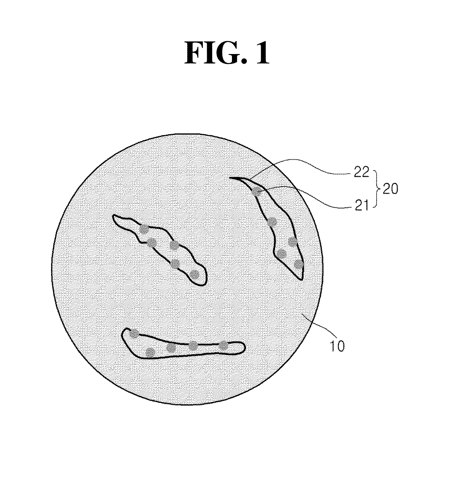
[0027]The silicon-carbon-polymer matrix slurry according to the present invention may include silicon bound to the carbon particles to be significantly uniformly dispersed without layer separation, and the silicon-carbon-polymer carbonized matrix formed from the silicon-carbon-polymer matrix slurry may have a network structure which is cross-linked by a cross-linking agent, such that when the carbon-silicon composite including the silicon-carbon-polymer carbonized matrix is used as an anode active material for a secondary battery, charge capacity, and charge and discharge stability of the secondary battery may be further improved.

Problems solved by technology

However, as compared with a carbon-based material, silicon has deteriorated cycle property, which is still an obstacle to practical use.
The reason is because when inorganic particles such as silicon for an anode active material are directly used as a material for absorption and release of lithium, conductivity between active materials is deteriorated due to a change in volume during a charge and discharge process, or the anode active material is separated from an anode current collector.
In addition, when the lithium is released by a discharge process, the inorganic particles are contracted, and when the charge and discharge cycles are repeated, electrical insulation may occur due to empty space generated between the inorganic particles and the anode active material to cause rapid deterioration in lifespan, and therefore, the inorganic particles have a serious problem in being used for a secondary battery.

Method used


Image

  • Carbon-silicon composite and manufacturing method thereof
  • Carbon-silicon composite and manufacturing method thereof
  • Carbon-silicon composite and manufacturing method thereof

Examples


experimental example

[0125]Charge and discharge properties of the secondary batteries manufactured by Example 1 and Comparative Examples 2 and 3 were tested under the following conditions.

[0126]When it is assumed that 300 mA per 1 g is 1 C, charge conditions were controlled by a constant current at 0.2 C up to 0.01V, and a constant voltage at 0.01V up to 0.01 C, and discharge conditions were measured by the constant current at 0.2 C up to 1.5V.

[0127]FIG. 4 is a graph illustrating results obtained by measuring discharge capacity according to cycle number on secondary batteries manufactured by Example 1 and Comparative Examples 2 and 3. Table 1 below shows results of initial charge capacity (mAh / g), and results of charge capacity retention rate (%) after 10 cycles obtained by converting a charge capacity retention rate after 10 cycles in relation to the initial charge capacity, into percent (%).

TABLE 1ComparativeComparativeExample 1Example 2Example 3Initial Charge674428290Capacity(mAh / g)Charge94.597.995.0...


PUM

PropertyMeasurementUnit
mass particle size distributionaaaaaaaaaa
cumulative mass particle size distributionaaaaaaaaaa
diameteraaaaaaaaaa

Abstract

Disclosed herein are a manufacturing method of a carbon-silicon composite, the manufacturing method including: (a) preparing a silicon-carbon-polymer matrix slurry including a silicon slurry, carbon particles, a monomer of polymer, and a cross-linking agent; (b) performing a heat treatment process on the silicon-carbon-polymer matrix slurry to manufacture a silicon-carbon-polymer carbonized matrix; (c) pulverizing the silicon-carbon-polymer carbonized matrix to manufacture a silicon-carbon-polymer carbonized matrix structure; and (d) mixing the silicon-carbon-polymer carbonized matrix structure with a first carbon raw material and performing a carbonization process to manufacture a carbon-silicon composite, the carbon-silicon composite, an anode for a secondary battery manufactured by applying the carbon-silicon composite, and a secondary battery including the anode for a secondary battery.

Description

CROSS REFERENCE TO RELATED APPLICATION[0001]This application claims the benefit of Korean Patent Application No. 10-2014-0116577, filed on Sep. 3, 2014, entitled “CARBON-SILICON COMPOSITE AND MANUFACTURING METHOD THEREOF”, which is hereby incorporated by reference in its entirety into this application.TECHNICAL FIELD[0002]The present invention relates to a carbon-silicon composite and a manufacturing method thereof.BACKGROUND ART[0003]An anode material of a lithium secondary battery capable of implementing high capacity is required to be used for a battery for an information technology (IT) equipment or a battery for an automobile. Accordingly, silicon has attracted attention as the anode material of the lithium secondary battery with high capacity. For example, it is known that pure silicon has a high theoretical capacity of 4200 mAh / g.[0004]However, as compared with a carbon-based material, silicon has deteriorated cycle property, which is still an obstacle to practical use. The r...

Claims


Application Information

Patent Timeline
Patent Type & Authority Applications(United States)
IPC IPC(8): H01M4/38B01J6/00H01M4/583H01M10/052
CPCH01M4/386B01J6/00H01M2220/30H01M10/052H01M2220/20H01M4/583H01M4/364H01M4/587H01M10/0525H01M4/134H01M4/62Y02E60/10C01B32/05C01B33/02H01M4/0471H01M4/13H01M4/133H01M4/1393H01M4/1395H01M4/38
Inventor JUNG, SUNG-HOKIM, YO-SEOPJEONG, EUN-HYEHA, JEONG-HYUN
Owner OCI
Why Eureka
Try Eureka