
High-frequency power supply device

a power supply device and high-frequency technology, applied in the direction of optical radiation measurement, instruments, spectrophotometry/monochromators, etc., can solve the problems of poor efficiency of the amplifier element using the vacuum tube, the inability to calibrate, and the increase in the cost of comparison, so as to avoid the occurrence of defects, accurate control, and the effect of low cos

Active Publication Date: 2016-03-03
SHIMADZU CORP
View PDF6 Cites 6 Cited by
  • Summary
  • Abstract
  • Description
  • Claims
  • Application Information

AI Technical Summary

Benefits of technology

The present invention is a high-frequency power supply device that can accurately control plasma input power, regardless of the state of the plasma generating gas or the analysis sample. It uses a switching circuit with a semiconductor device, which is an inexpensive configuration compared to a vacuum tube. The device is also reliable against load variation and can easily monitor changes in the state of plasma. The technical effects of the invention are improved accuracy, reliability, and ease of monitoring.

Problems solved by technology

According to the conventional configuration as described above, it is not possible to calibrate the output power of the high-frequency power supply in advance by using a power meter with 50 Ω, and thus a configuration for accurately controlling the plasma input power becomes necessary.
However, the amplifier element using a vacuum tube is poor in efficiency, and there are problems regarding the life of the vacuum tube and the increase in the cost compared with a switching circuit using a semiconductor device, or the like.
However, as described above, with a high-frequency power supply device for generating plasma, the impedance of the induction coil changes, and thus, due to a load variation of the switching circuit, the voltage amplitude between the drain and the source of the MOSFET is changed, resulting in possible breakage due to the maximum rating of the device being exceeded.

Method used


Image

  • High-frequency power supply device
  • High-frequency power supply device
  • High-frequency power supply device

Examples


Embodiment Construction

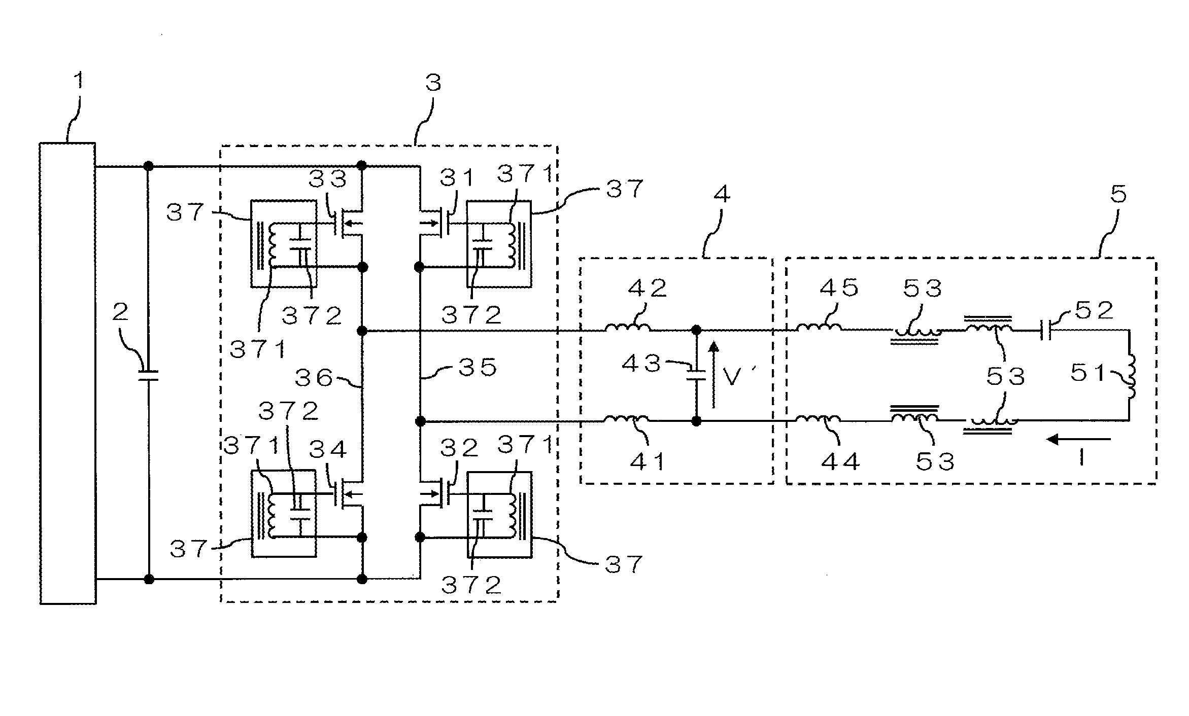
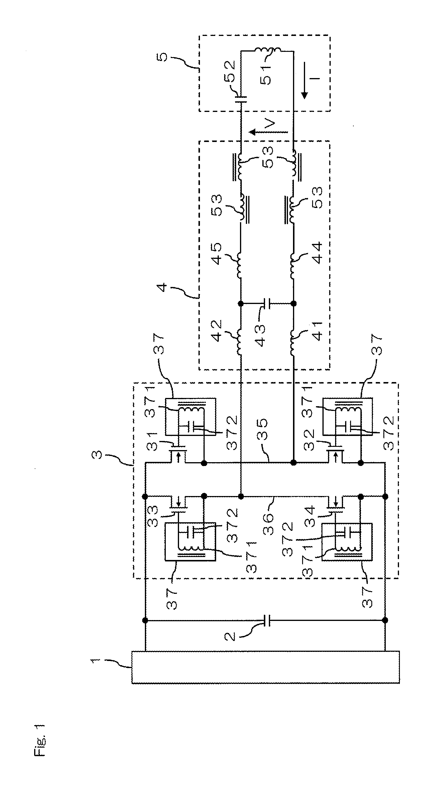
[0039]FIG. 1 is a circuit diagram showing a configuration example of a high-frequency power supply device according to an embodiment of the present invention. This high-frequency power supply device may be applied to an analysis device such as an inductively coupled plasma (ICP) emission spectrometer, and is a high-frequency power supply device provided with a DC power supply 1, a bypass capacitor 2, a switching circuit 3, an impedance conversion circuit 4, a series resonant circuit 5, and the like.

[0040]The DC power supply 1 sets a DC voltage of the switching circuit 3, and determines the high-frequency power to be supplied to the series resonant circuit 5. The bypass capacitor 2 is arranged between the DC power supply 1 and the switching circuit 3, and secures a low-impedance high-frequency current path.

[0041]The series resonant circuit 5 includes an induction coil 51, and a capacitor 52 that is connected in series to the induction coil 51. The induction coil 51 included in the se...


PUM


Abstract

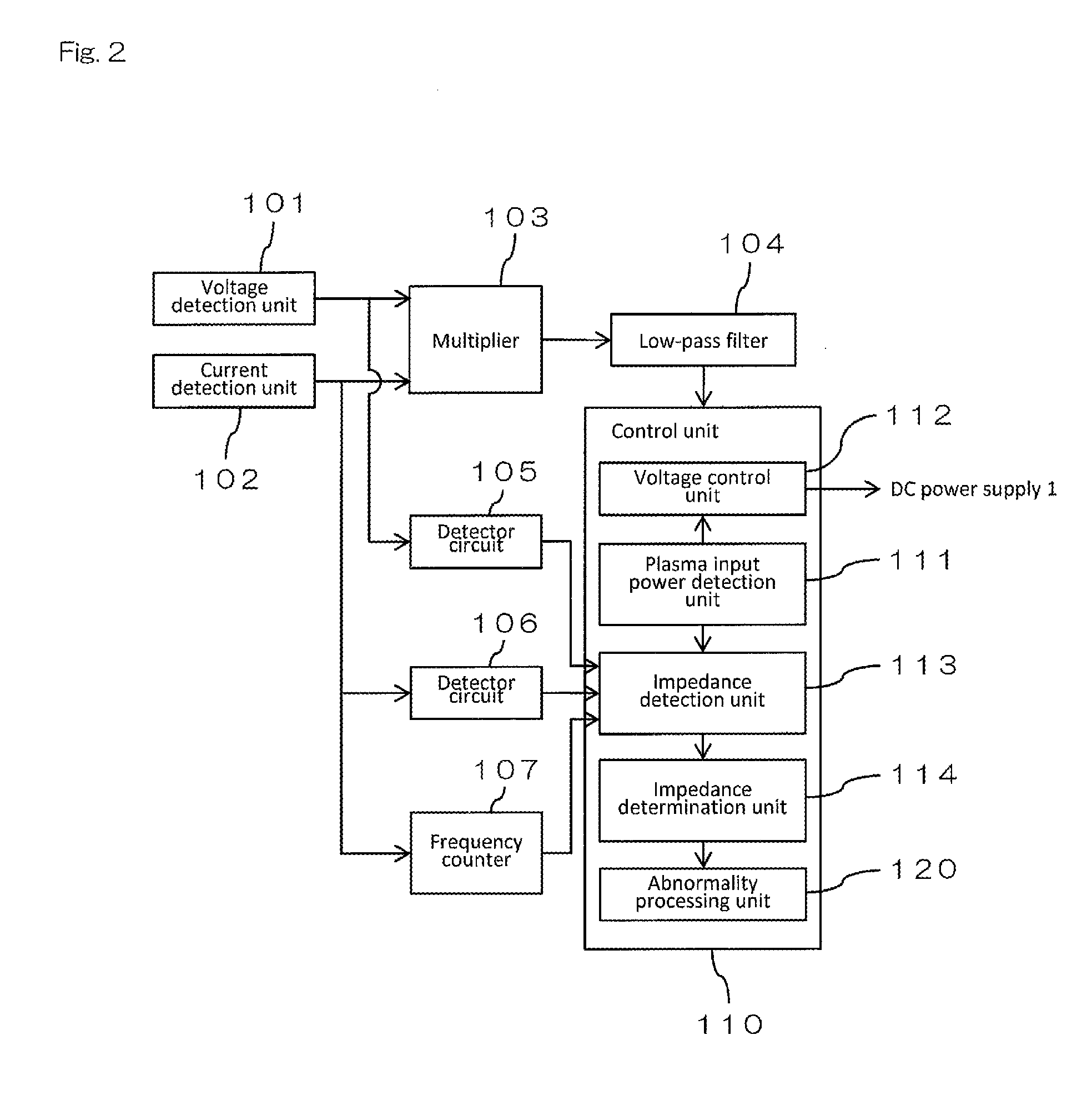
A high-frequency input voltage and a high-frequency input current to a series resonant circuit are detected by a voltage detection unit and a current detection unit, respectively, and plasma input power is detected by a plasma input power detection unit based on the detected high-frequency input voltage and high-frequency input current. By directly detecting the plasma input power in this manner, the plasma input power may be accurately controlled regardless of the state of a plasma-generating gas or an analysis sample. Also, use of a switching circuit including a semiconductor device allows an inexpensive configuration compared with a configuration where a vacuum tube or the like is used.

Description

BACKGROUND OF THE INVENTION[0001]1. Field of the Invention[0002]The present invention relates to a high-frequency power supply device for generating plasma by supplying high-frequency power to an induction coil included in a resonant circuit from a DC power supply via a switching circuit.[0003]2. Description of the Related Art[0004]For example, an analysis device such as an inductively coupled plasma (ICP) emission spectrometer has a configuration of generating plasma at a plasma torch by supplying high-frequency power to an induction coil included in a resonant circuit (for example, see JP-A-10-214698, JP-W-2009-537829, JP-A-6-20793, and WO 2012 / 039035 A). A high-frequency electromagnetic field is generated by the high-frequency power supplied to the induction coil, and an induced current flows by charged particles in plasma being accelerated, and plasma is thereby heated.[0005]In the case of such a configuration, the impedance (resistance component and reactance component) of the ...

Claims


Application Information

Patent Timeline
Patent Type & Authority Applications(United States)
IPC IPC(8): H05H1/46G01J3/02H01J37/244H01J37/32
CPCH05H1/46H01J37/321H05H2001/4682G01J3/027H05H2001/4652H01J37/244H05H1/0037H05H1/36H01J37/32174H01J37/32183G01J3/10G01J3/443H05H1/4652H05H2242/20
Inventor HABU, TOSHIYA
Owner SHIMADZU CORP
Learn More