RNA Microchip Detection Using Nanoparticle-Assisted Signal Amplification

a microchip and signal amplification technology, applied in the field of nucleic acid detection and analysis, can solve the problems of ineffective differentiation of antigen-antibody immunological assay, time-consuming culture-based methods, and inability to effectively differentiate, so as to increase the amount of second label at the site, increase the detection sensitivity, the effect of easy detection

Inactive Publication Date: 2016-03-10
GEORGIA STATE UNIV RES FOUND INC
View PDF1 Cites 4 Cited by
  • Summary
  • Abstract
  • Description
  • Claims
  • Application Information

AI Technical Summary

Benefits of technology

[0012]By using another conjugate that can aggregate on or at the site of the second label, the amount of second label at the site is increased, increasing the sensitivity of the detection and making detection easier. This can be accomplished, for example, by bringing into contact the probe array and a detection conjugate, where detection conjugate comprises an aggregator, and where the aggregator mediates aggregation of detection conjugates on the label conjugate. An example of a useful combination of second label and detection conjugate are gold nanoparticle as the second label and a silver nanoparticle as the detection conjugate. In this example, the silver nanoparticle is the aggregator. The silver nanoparticle reacts with the gold nanoparticle to accumulate silver nanoparticles at the site of the gold nanoparticles. The accumulation of the reacted silver nanoparticles can be sufficient to detect with the naked eye.
[0013]Rapid and accurate detection of pathogens, such as RNA viruses at the point of care, will allow proper patient treatment and save lives. The disclosed RNA microchip can directly detect RNA without reverse transcription and PCR amplification. The disclosed RNA microchip can use nanoparticle-assisted signal amplification. The disclosed RNA microchip technology is simple and accurate and can differentiate single-nucleotide difference. In some forms, RNA can be sensitively detected within 1 hour, and the signal can be detected by naked eye. The visual readout format and simplicity make the disclosed RNA microchip technology well suited for the rapid and accurate detection of pathogens in clinics and in the field with minimum resources.
[0015]The disclosed methods can be aided by using solid state substrates to which the chimeric probes are immobilized as the probe array. The location of particular chimeric probes allows identification of the RNA molecule detected since the sequence of the chimeric probe at a location where label is detected is known. By including multiple different chimeric probes on a probe array, multiple different RNA molecules can be detected. Related RNA molecules can be detected collectively by grouping different chimeric probes specific to the different RNA molecules at eh same location on the probe array. This can simplify detection of targets that, for example, have variable sequences.

Problems solved by technology

Viral and bacterial pathogen detection for infectious disease rapid diagnosis is a major healthcare challenge.
Culture-based methods are time-consuming and need normally 2-3 days before obtaining conclusions (March and Ratnam, J Clin Microbiol, 23, 869 (1986)).
Antigen-antibody-based immunological assay (i.e., ELISA) cannot effectively differentiate the subtle differences between different strains, though it is rapid and robust.
However, they don't detect RNAs directly, and reverse transcription (RT) and multiple steps are required.
PCR amplification may cause false positive results due to the lack of strict contamination control.
Furthermore, current methods for direct RNA detection, such as Northern blot, RNase protection assay, microRNA profiling, and direct RNA sequencing (Nelson et al., Nat Methods, 1, 155 (2004); Sandelin et al., Nat Rev Genet, 8, 424 (2007); Ozsolak et al., Nature, 461, 814 (2009)), are labor-intensive, time-consuming, costly and / or instrument-intensive.
These approaches are not well-suited for rapid and accurate RNA detection, especially for point-of-care diagnosis and field applications.
However, the RNA sample preparation and convenient detection are still complicated and time-consuming, which are major challenges in direct RNA detection for the point-of-care pathogen and disease diagnosis.

Method used


Image

  • RNA Microchip Detection Using Nanoparticle-Assisted Signal Amplification
  • RNA Microchip Detection Using Nanoparticle-Assisted Signal Amplification
  • RNA Microchip Detection Using Nanoparticle-Assisted Signal Amplification

Examples


examples

[0122]A. RNA Microchip Detection Using Nanoparticle-Assisted Signal Amplification

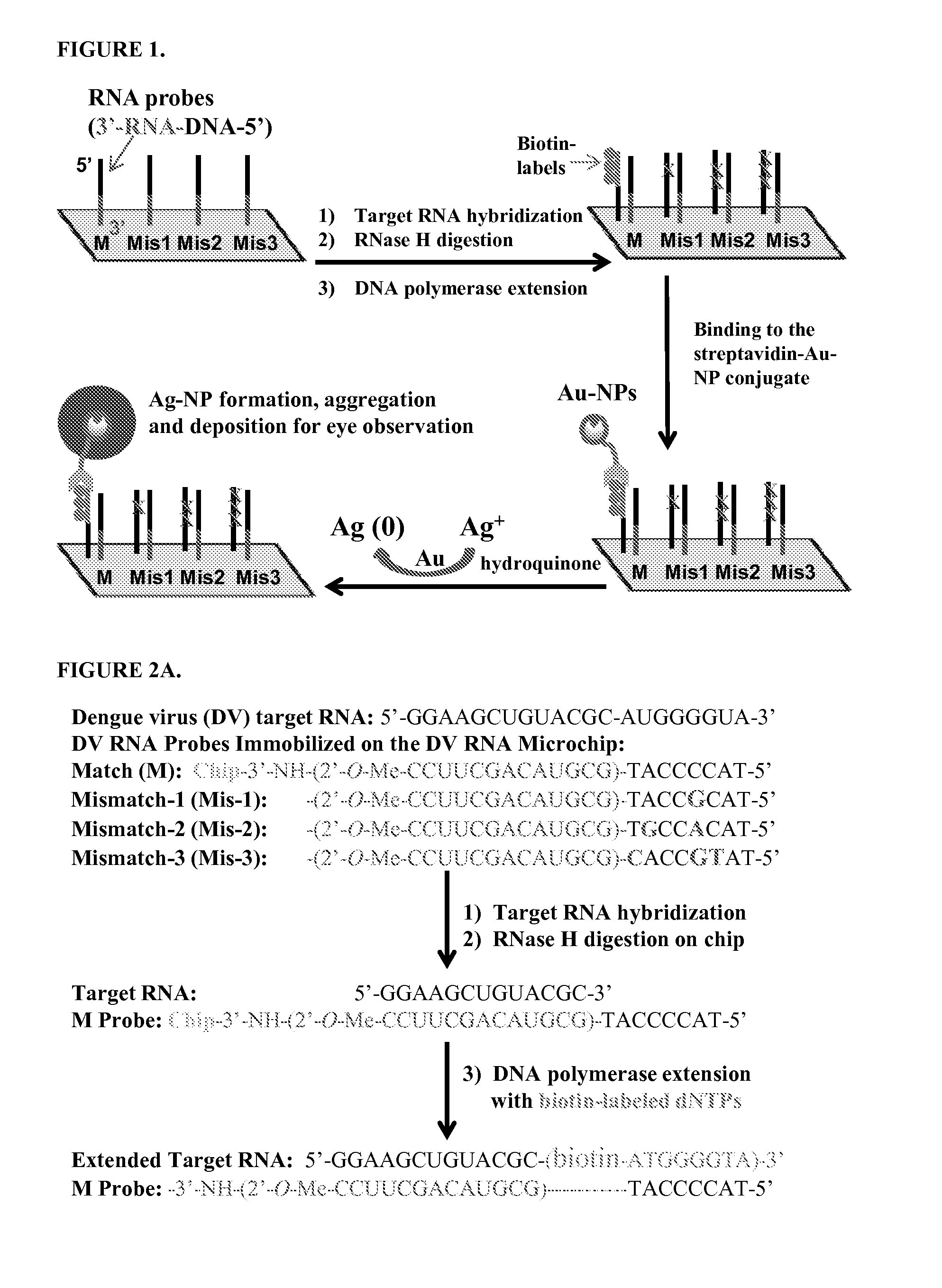
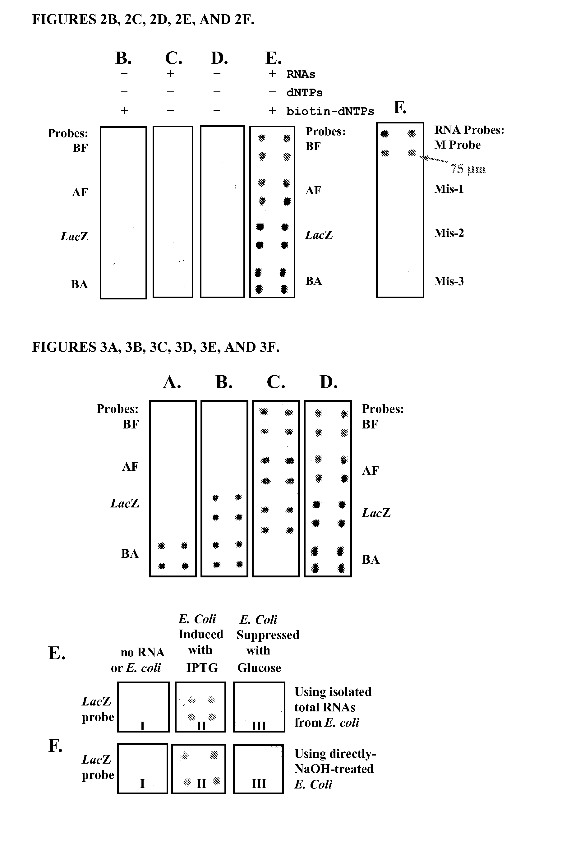
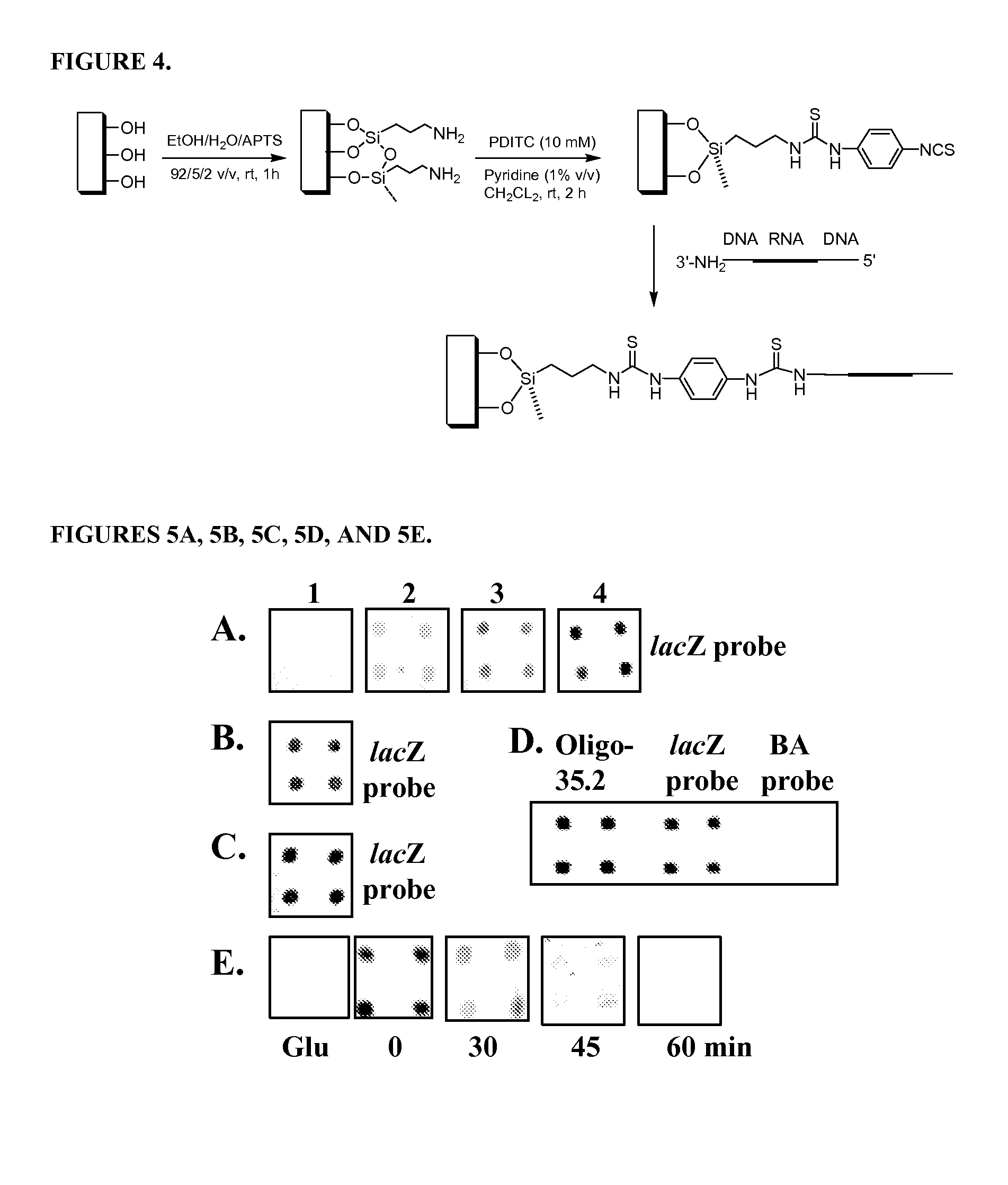
[0123]This example describes an example of the disclosed RNA microchip used to directly detect RNA via direct visualization and nanoparticle-assisted signal amplification. This technology is simple and accurate and it can efficiently differentiate single-nucleotide difference. The RNA sample preparation is simple and can be accomplished in 5 min. The disclosed rapid RNA detection can be completed within 45 min (including sample preparation time) and have the detection sensitivity at the low fmole level. In addition, the detection signals can be observed by naked eye or with a magnifying glass. This approach is PCR-free, easy to perform and cost-effective. Moreover, the strategy does not require sophisticated equipment and can be used to help monitor disinfection treatment. The visual detection format and simplicity make this RNA microchip technology well suited for rapid and accurate detection of pathog...


PUM

PropertyMeasurementUnit
sizeaaaaaaaaaa
diameteraaaaaaaaaa
diameteraaaaaaaaaa

Abstract

Disclosed are methods and materials for detecting RNA in a sample. In some forms, the method involves (a) bringing into contact the sample and a probe array, (b) bringing into contact the probe array and a ribonuclease specific for RNA / DNA hybrids (such as RNase H), (c) bringing into contact the probe array, labeled nucleotides, and a nucleic acid polymerase capable of extending a RNA strand using a DNA template and capable of incorporating the labeled nucleotides in the extension from the RNA strand (such as Klenow fragment DNA polymerase), and (d) detecting the labeled nucleotides in the extended nucleic acid strand. The probe array comprises one or more chimeric probes. The chimeric probes comprise a DNA region and a RNA region, where the DNA region and the RNA region are contiguous and where the DNA region is 5′ of the RNA region. The chimeric probe can also include a second DNA region. The second DNA region can also be contiguous with the RNA region and can be 3′ of the RNA region.

Description

CROSS—REFERENCE TO RELATED APPLICATIONS[0001]This application claims benefit of U.S. Provisional Application No. 61 / 808,447, filed Apr. 4, 2013. Application No. 61 / 808,447, filed Apr. 4, 2013, is hereby incorporated herein by reference in its entirety.REFERENCE TO SEQUENCE LISTING[0002]The Sequence Listing submitted Apr. 4, 2014 as a text file named “GSURF—2013—17_PCT_Sequence_Listing.txt,” created on Apr. 4, 2014, and having a size of 4,889 bytes is hereby incorporated by reference pursuant to 37 C.F.R. §1.52(e)(5).FIELD OF THE INVENTION[0003]The disclosed invention is generally in the field of nucleic acid detection and analysis and specifically in the area of RNA detection and analysis.BACKGROUND OF THE INVENTION[0004]Natural pandemics (for example, West Nile virus (WNV) and flu pandemics) (Pripuzova et al., PLoS One, 7, e43246 (2012); Wheeler et al., Am J Trop Med Hyg, 87, 559 (2012); Brault et al., J Med Entomol, 49, 939 (2012); Kesavaraju et al., Am J Trop Med Hyg, 87, 359 (20...

Claims


Application Information

Patent Timeline
Patent Type & Authority Applications(United States)
IPC IPC(8): C12Q1/68
CPCC12Q1/6837B82Y5/00C12Q2521/101C12Q2521/327C12Q2525/121C12Q2563/131
Inventor HUANG, ZHEN
Owner GEORGIA STATE UNIV RES FOUND INC
Why Eureka
Try Eureka