Thermal reduction apparatus for metal production, gate device, condensing system, and control method thereof

a technology of thermal reduction apparatus and metal, which is applied in the direction of preheating charges, blast furnaces, charges, etc., can solve the problems of limited productivity per day and difficulty in consistently automating processes, and achieve the effect of reducing continuously and thermally, and maximizing productivity

Active Publication Date: 2016-03-10
RES INST OF IND SCI & TECH
View PDF5 Cites 10 Cited by
  • Summary
  • Abstract
  • Description
  • Claims
  • Application Information

AI Technical Summary

Benefits of technology

[0083]The to-be-reduced materials may be continuously supplied to the reducing unit, thereby continuously and thermally reducing a metal. Therefore, the to-be-reduced materials are continuously and thermally reduced, thereby maximizing productivity.
[0084]In addition, in a case in which the heating is carried out at the outside using a retort, there is a problem in that the retort is damaged due to heat. However, in the case of the thermal reduction apparatus according to the exemplary embodiment, the to-be-reduced material is heated in the thermal reduction apparatus, thereby increasing a lifespan of the thermal reduction apparatus.
[0085]In addition, it is possible to stably open and close the gate under vacuum at a high temperature, and to prevent contamination or damage to the sealing member of the gate due to the metal vapor of the reducing unit.
[0086]Further, it is possible to improve efficiency in producing magnesium by simplifying a magnesium process, and to reduce costs required to produce magnesium by allowing the magnesium condenser to be used repeatedly.
[0087]By using the plurality of condensing devices, the magnesium vapor is condensed and the magnesium vapor is controlled by the control valve so as to flow only into the condensing device in which the condensing process is being carried out, thereby preventing contamination in the condensing device and reducing consumption of the magnesium vapor.
[0088]In addition, the plurality of condensing devices alternately and continuously perform the condensing process and the process of removing the magnesium crown, thereby improving efficiency in producing the magnesium crown.

Problems solved by technology

However, in the case of this batch type of manufacturing apparatus, there is a limitation in that productivity per day is limited because the reduction is carried out for a predetermined time, a thermal loss occurs in the retort because of discontinuous loading and unloading, and there is difficulty in automating processes consistently, and as a result, there is a need for a method of continuously and thermally reducing the magnesium.

Method used


Image

  • Thermal reduction apparatus for metal production, gate device, condensing system, and control method thereof
  • Thermal reduction apparatus for metal production, gate device, condensing system, and control method thereof
  • Thermal reduction apparatus for metal production, gate device, condensing system, and control method thereof

Examples


first exemplary embodiment

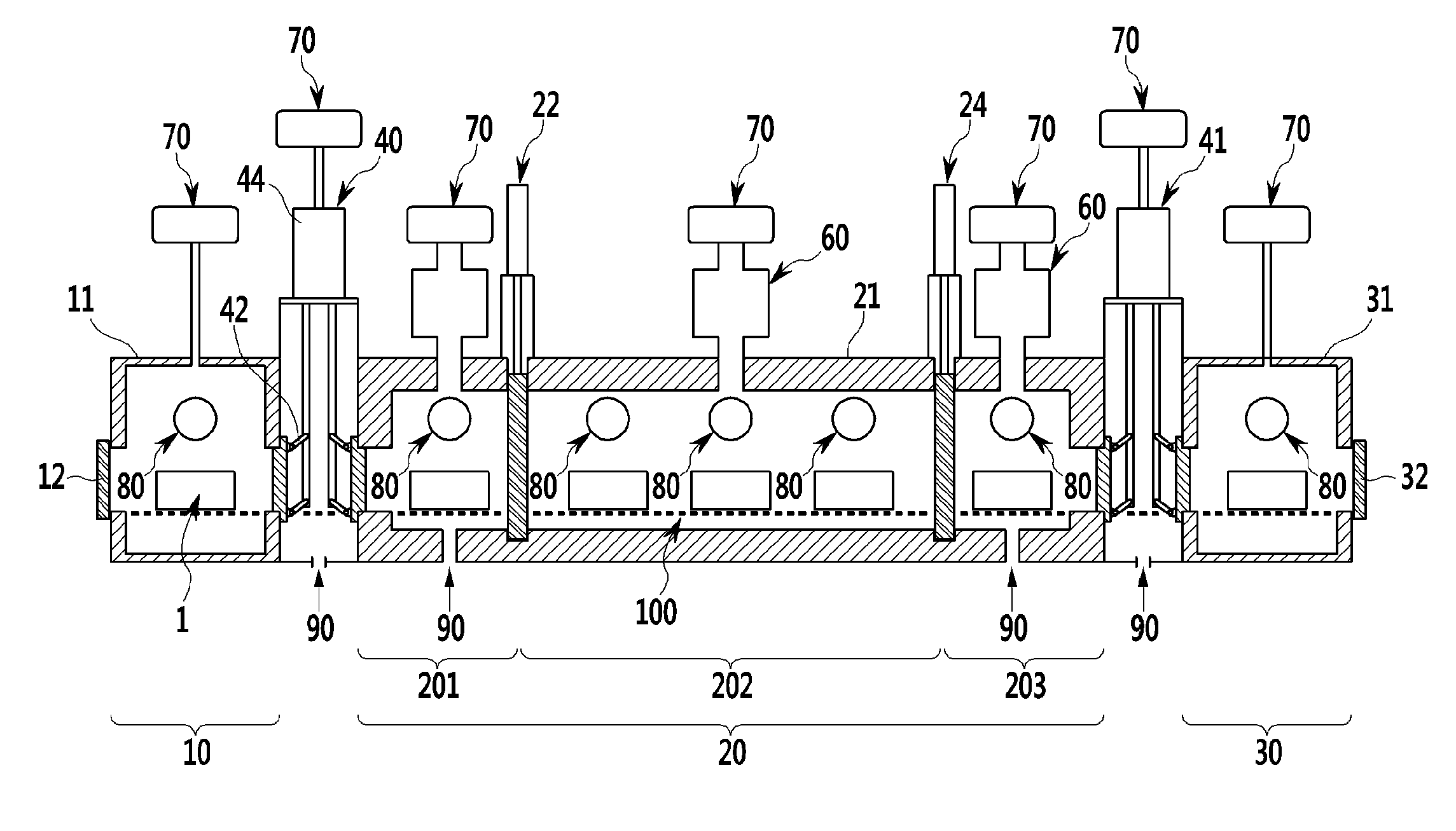
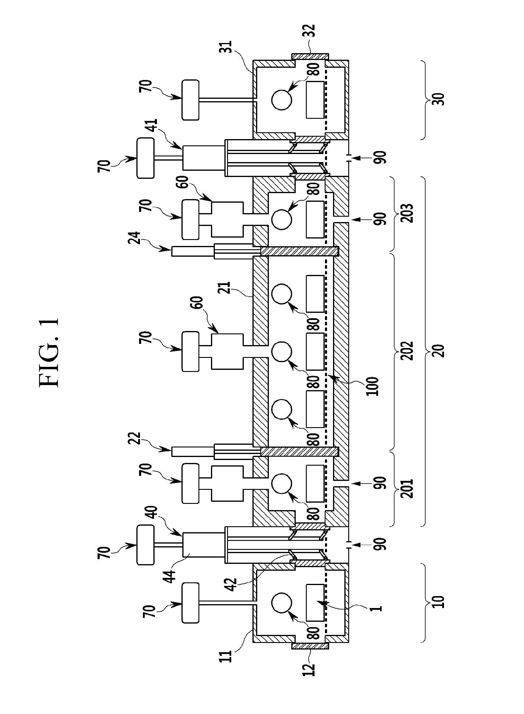
[0107]FIG. 1 is a configuration diagram of a thermal reduction apparatus according to an exemplary embodiment of the present invention.

[0108]Referring to FIG. 1, the thermal reduction apparatus according to the present exemplary embodiment may include: a preheating unit 10 which preheats a to-be-reduced material 1 and loads the to-be-reduced material 1 into a reducing unit 20; the reducing unit 20 which is connected to the preheating unit 10 and in which a thermal reduction reaction of the to-be-reduced material occurs; a cooling unit 30 which is connected to the reducing unit 20 and which unloads the to-be-reduced material 1 loaded into the cooling unit 30 to the outside; a first gate device 40 which is installed between the preheating unit 10 and the reducing unit 20; a second gate device 41 which is installed between the reducing unit 20 and the cooling unit 30; and a condensing device 60 which is connected to the reducing unit 20 and which condenses a metal vapor. The thermal re...

second exemplary embodiment

[0150]FIG. 3 illustrates a configuration of a thermal reduction apparatus according to the present exemplary embodiment.

[0151]Referring to FIG. 3, the thermal reduction apparatus according to the present exemplary embodiment includes: a preheating unit 210 which preheats a to-be-reduced material; a reducing unit 220 which is connected to the preheating unit and in which a thermal reduction reaction of the to-be-reduced material occurs; a cooling unit 230 which is connected to the reducing unit and from which the to-be-reduced material loaded into the cooling unit 230 is unloaded; a first gate valve 240 which is installed between the preheating unit and the reducing unit; a second gate valve 241 which is installed between the reducing unit and the cooling unit; and a condensing device 260 which is connected to the reducing unit and condenses a metal vapor.

[0152]For example, the to-be-reduced material may be accommodated in a briquette box BB having a predetermined size and an accommo...


PUM

PropertyMeasurementUnit
temperatureaaaaaaaaaa

Abstract

Disclosed is a thermal reduction apparatus. The thermal reduction apparatus according to the exemplary embodiment includes: a preheating unit which preheats a to-be-reduced material and loads the to-be-reduced material into a reducing unit; the reducing unit which is connected to the preheating unit and in which a thermal reduction reaction of the to-be-reduced material occurs; a cooling unit which is connected to the reducing unit and from which the to-be-reduced material flowing into the cooling unit is unloaded to the outside; a gate device which is installed between the preheating unit and the reducing unit; a gate device which is installed between the reducing unit and the cooling unit; a condensing device which is connected to the reducing unit and condenses a metal vapor; a first blocking unit which is installed in the reducing unit; and a second blocking unit which is installed in the reducing unit so as to be spaced apart from the first blocking unit.

Description

CROSS-REFERENCE TO RELATED APPLICATION[0001]This application claims priority to and the benefit of Korean Patent Application Nos. 10-2014-0117736, 10-2014-0186547, 10-2014-0186441, and 10-2014-187655 filed in the Korean Intellectual Property Office on Sep. 4, 2014, Dec. 22, 2014, Dec. 22, 2014, and Dec. 23, 2014, the entire contents of which are incorporated herein by reference. In addition, the entire contents of Korean Patent Application No. 10-2013-0159587 filed in the Korean Intellectual Property Office on Dec. 19, 2013 is incorporated herein by reference.BACKGROUND OF THE INVENTION[0002](a) Field of the Invention[0003]The present invention relates to a thermal reduction apparatus for metal production, a gate device of the thermal reduction apparatus, a condensing system of the thermal reduction apparatus, and a control method thereof.[0004](b) Description of the Related Art[0005]A method of refining metal may be classified into pyrometallurgy, hydrometallurgy, electrometallurgy...

Claims


Application Information

Patent Timeline
Patent Type & Authority Applications(United States)
IPC IPC(8): F27B19/02C22B1/00C22B5/16C22B9/04F27D7/06F27D13/00F27D15/02
CPCF27B19/02C22B5/16C22B1/00F27D7/06F27M2003/155F27D15/02C22B9/04F27D2007/066F27M2003/15F27D13/00C22B26/22F27B9/028F27B9/042F27B9/2407F27B9/40F27B2017/0091F27D3/04F27D3/12F27D99/0073
Inventor CHOO, DONG KYUNKIM, YOUNG ILCHO, KIL WONCHOO, WUNG YONGPARK, JONG MINPARK, JAE SINHAN, GILSOOCHOI, GOOD-SUNLEE, GYU CHANGPARK, DAE KYUKIM, MOON CHUL
Owner RES INST OF IND SCI & TECH
Why Eureka
Try Eureka