Wireless power transmission device
a power transmission device and wireless technology, applied in the direction of inductances, instruments, transportation and packaging, etc., can solve the problems of excessive heat in metal foreign objects and/or power supply modules, and achieve the effect of reducing the magnetic field strength
- Summary
- Abstract
- Description
- Claims
- Application Information
AI Technical Summary
Benefits of technology
Problems solved by technology
Method used
Image

Examples
embodiment
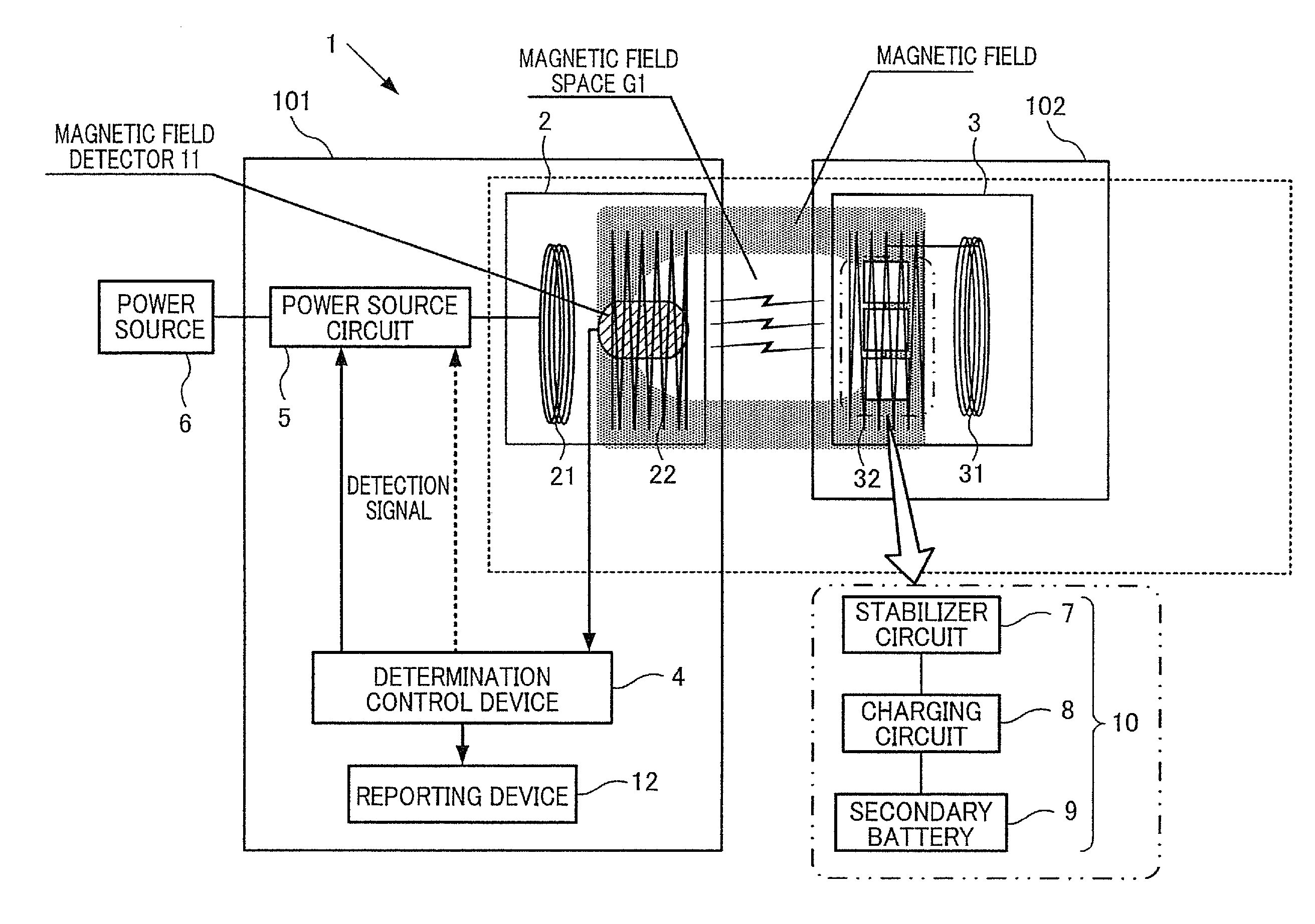
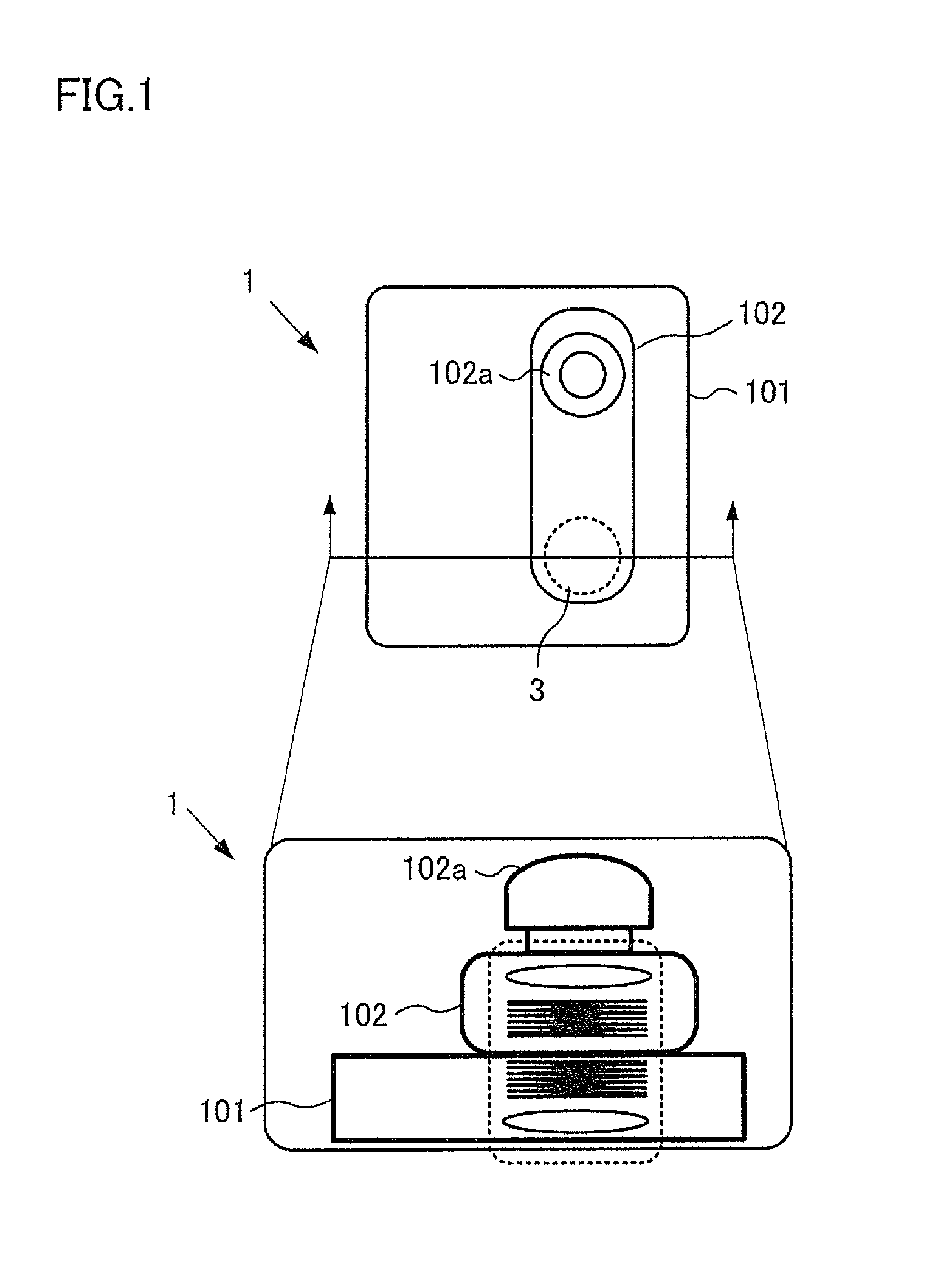
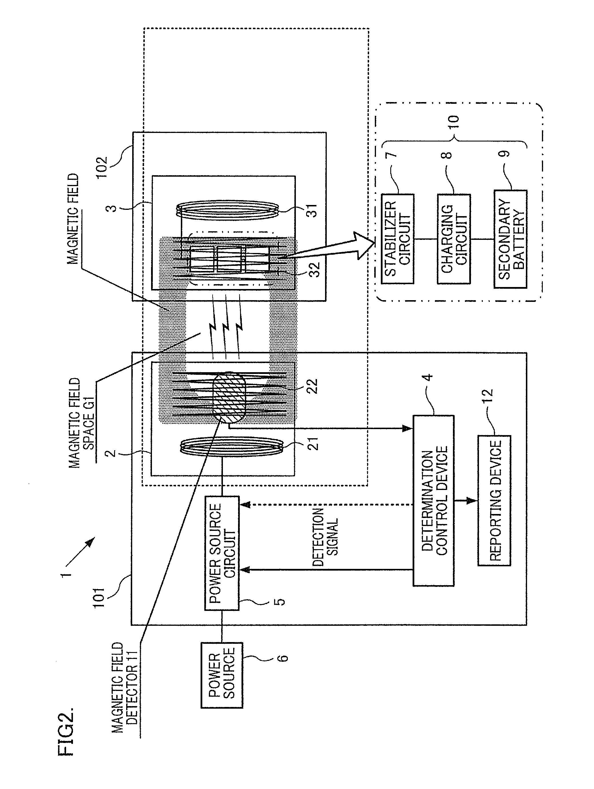
[0063]The wireless power transmission apparatus 1 is configured to form a magnetic field space G1 (G2) having a lower magnetic field strength than that of nearby portions, and the apparatus 1 includes, as essential components, a power-supplying module 2 including a power-supplying resonator 22, and a power-receiving module 3 including a power-receiving resonator 32. In this embodiment, a charger 101 having the power-supplying module 2 mounted therein and a wireless headset 102 having the power-receiving module 3 mounted therein will be described, as an example of the wireless power transmission apparatus 1. FIG. 1 illustrates the charger 101 and the wireless headset 102 at the time of charging. FIG. 2 is a block diagram illustrating the structure of the wireless power transmission apparatus 1. FIG. 3 is an explanatory diagram illustrating the power-supplying module 2 and the power-receiving module 3, in the form of an equivalent circuit.
(Structures of Charger 101 and Wireless Headse...
experiment 1
(Measurement Experiment 1)
[0093]In Measurement Experiment 1, as shown in FIG. 11 to FIG. 13, a Hall-effect magnetic sensor 11A (made by Allegro Microsystems, LLC, A1324LUA, linear sensor) was disposed on the inner circumference side of the power-supplying resonator 22, and output voltages of the Hall-effect magnetic sensor 11A in the normal charging state, the standby state, and the abnormal state are measured using an oscilloscope (made by Agilent Technology, MSO-X3054A) connected to the Hall-effect magnetic sensor 11A. A change in the measured output voltage can be regarded as a change in the magnetic field strength because the output voltage of the Hall-effect magnetic sensor 11A is proportional to the magnetic field strength.
[0094]In Measurement Experiment 1, as shown in FIG. 14, the output voltage of the Hall-effect magnetic sensor 11A was measured under a voltage of DC 5V. When power supply is not performed from the power source 6 to the power-supplying module 2 under this con...
experiment 2
(Measurement Experiment 2)
[0096]In Measurement Experiment 2, a magnetism detecting coil 11B is disposed on the inner circumference side of the power-supplying resonator 22, and output voltages of the magnetism detecting coil 11B in the normal charging state, the standby state, and the abnormal state were measured using the oscilloscope (made by Agilent Technology, MSO-X3054A) connected to the magnetism detecting coil 11B. The change in the measured output voltage can be regarded as the change in the magnetic field strength because the output voltage of the magnetism detecting coil 11B is proportional to the magnetic field strength. The magnetism detecting coil 11B is an RL circuit (R=1.22Ω, L=5 μH). For a coil portion thereof, copper wire material having a wire diameter of 0.12 mm is used, and its coil diameter is set to 5 mmφ.
[0097]In Measurement Experiment 2, as for the value of the measured output voltage, an amplitude Vp-p is regarded as a detection voltage p-p, as shown in FIG....
PUM
 Abstract
Description
Claims
Application Information
PatSnap Eureka turns technology decisions into work you can execute. Powered by our Innovation Knowledge Graph, it runs expert workflows across engineering, life sciences, materials and intellectual property. Get your review-ready output in minutes.


