Lighting device and luminaire

a technology of light source and light source, which is applied in the direction of electroluminescent light source, electric lighting source, and use of semiconductor lamps, can solve the problems of surge current flow in the resonant circuit, and achieve the effect of reducing ringing

Inactive Publication Date: 2016-03-10
PANASONIC INTELLECTUAL PROPERTY MANAGEMENT CO LTD
View PDF0 Cites 14 Cited by
  • Summary
  • Abstract
  • Description
  • Claims
  • Application Information

AI Technical Summary

Benefits of technology

[0009]The lighting device having the above configuration is capable of reducing ringing in the DC / DC converter including the resonant circuit.

Problems solved by technology

This causes a problem that a surge current flows in the resonant circuit including the switching elements and stresses circuit components such as the switching elements.

Method used


Image

  • Lighting device and luminaire
  • Lighting device and luminaire
  • Lighting device and luminaire

Examples


embodiment 1

1-1. Overall Configuration of Lighting Device

[0029]First, an overall configuration of lighting device 2 according to Embodiment 1 is described.

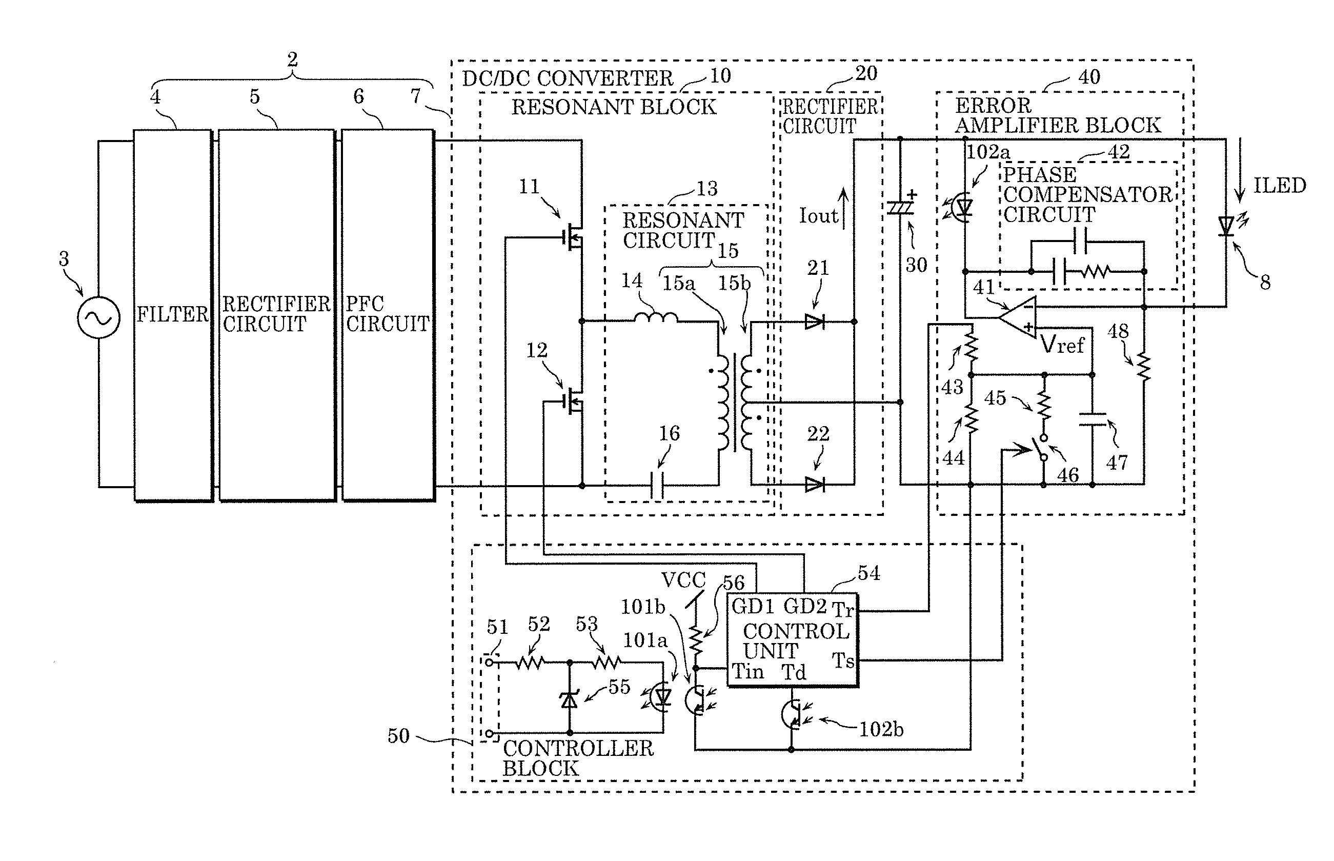
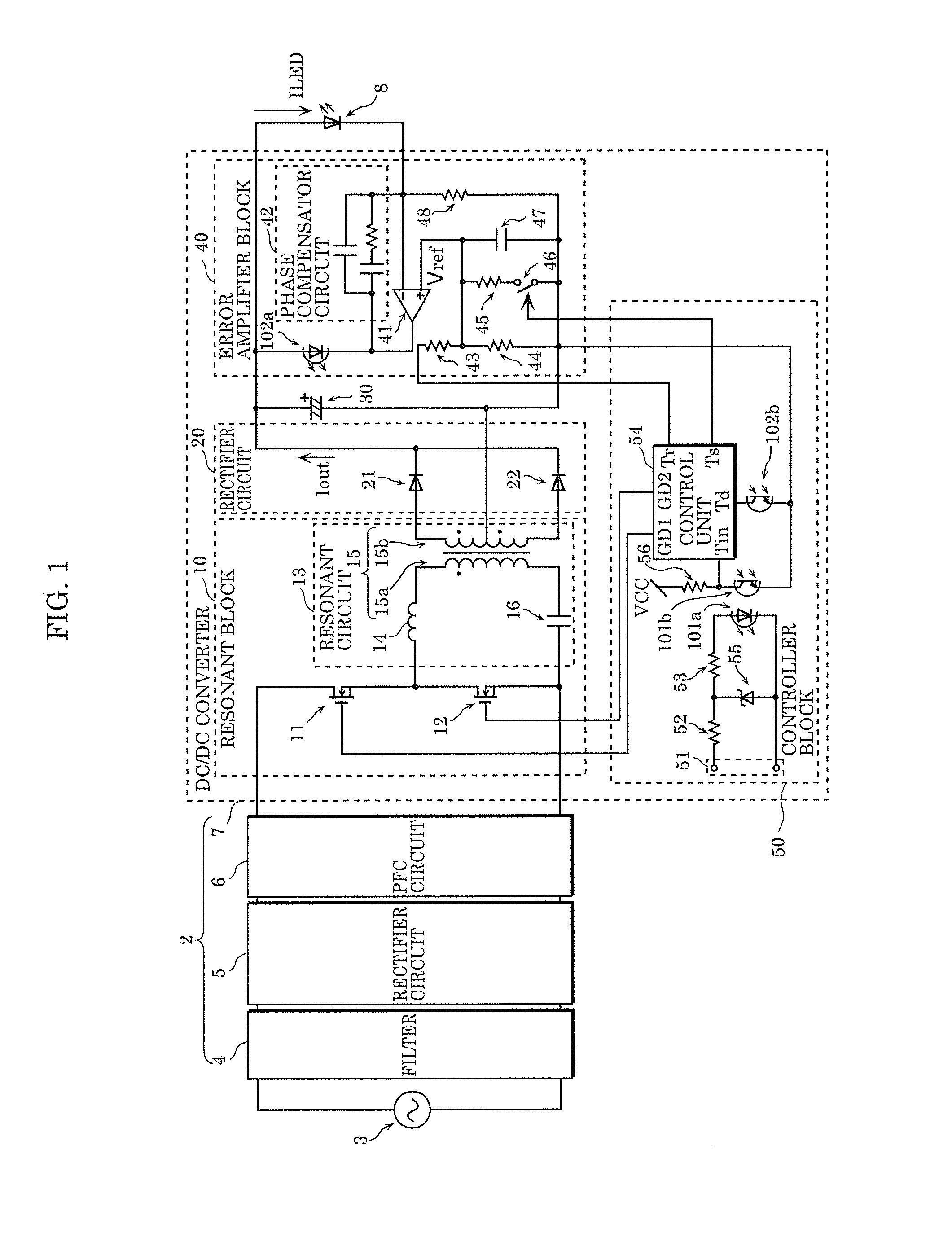
[0030]FIG. 1 is a circuit diagram illustrating a circuit configuration of lighting device 2 according to this embodiment. In the diagram, alternating current 3 (for example, a commercial power source) which generates an alternating voltage to be input to lighting device 2 and light emitting diode (LED) 8 that is an example of a solid light emitting element which receives supply of a current output from lighting device 2.

[0031]As illustrated in FIG. 1, lighting device 2 is a device which supplies a current to LED 8, and includes filter 4, rectifier circuit 5, power factor correction (PFC) circuit 6, and DC / DC converter 7.

[0032]Filter 4 is a filter which reduces leakage of a high frequency noise to outside lighting device 2. The high frequency noise is a noise generated by DC / DC converter 7 etc. due to a switching operation. Filter 4 used here ...

embodiment 2

[0092]Next, descriptions are given of lighting device 2a according to Embodiment 2. In the above Embodiment 1, the length of the frequency gradual decrease period is constant. However, when a non-switching period is short, most of charges accumulated in smoothing capacitor 30 are not emitted at the end time of a non-switching period (at the start time of a driving period), and thus smoothing capacitor 30 is in the state of receiving a high voltage applied thereto. Thus, in this case, ringing can be reduced even when the frequency gradual decrease period is short. In view of this, in this embodiment, the length of the frequency gradual decrease period is controlled according to a voltage etc. applied to the smoothing capacitor.

[0093]Hereinafter, lighting device 2a according to this embodiment is described mainly focused on elements different from those in lighting device 2 according to Embodiment 1, and the same elements as in Embodiment 1 are not described repeatedly.

2-1. Configurat...

embodiment 3

[0107]Next, descriptions are given of lighting device 2b according to Embodiment 3.

[0108]For the purpose of intermittently driving switching elements of a DC / DC converter in a lighting device, a smoothing capacitor is provided in an output part of the DC / DC converter in order to prevent output light flickers due to ripples of an output current. When the capacitance of the smoothing capacitor is increased excessively in order to reliably prevent light output from the lighting device from flickering, activation time of the lighting device is increased with the increase in the size of the smoothing capacitor and an increase in time constant. In view of this, a smoothing capacitor is generally provided in the DC / DC converter, and is controlled to perform intermittent driving at a high frequency in order to prevent ripples of an output current.

[0109]However, when an intermittent frequency which is a frequency in intermittent driving is increased in the case of deep dimming, the number of...


PUM


Abstract

A lighting device includes: a DC/DC converter including two switching elements connected in series and a resonant circuit connected to a connection point between the two switching elements; and a control unit configured to control driving of the two switching elements. The control unit is configured to: perform intermittent driving in which a switching period and a non-switching period are alternately repeated, the switching period being a period in which the control unit switches ON and OFF the two switching elements respectively and inversely; and the non-switching period being a period in which the control unit stops switching ON and OFF the two switching elements; and provide, in an initial part of the switching period, a frequency gradual decrease period in which a driving frequency for driving the two switching elements is gradually decreased.

Description

CROSS REFERENCE TO RELATED APPLICATION[0001]This application claims the benefit of priority of Japanese Patent Application Number 2014-184407, filed Sep. 10, 2014, the entire content of which is hereby incorporated by reference.BACKGROUND OF THE INVENTION[0002]1. Field of the Invention[0003]The present disclosure relates to a lighting device which supplies a current to a solid light emitting element, and a luminaire including the lighting device.[0004]2. Description of the Related Art[0005]Known lighting devices that supply a current to a solid light emitting element such as a light emitting diode (LED) include devices equipped with an AC / DC converter and a DC / DC converter connected to the AC / DC converter. These lighting devices are capable of dimming by controlling an output current of the DC / DC converter. Here, in the case where a dimming level is high (that is, the amount of light is small) in a lighting device, a peak current that flows in switching elements included in the DC / D...

Claims


Application Information

Patent Timeline
Patent Type & Authority Applications(United States)
IPC IPC(8): H05B44/00
CPCH05B33/0887H05B33/0815H05B45/10Y02B20/30H05B45/3725H05B45/382H05B45/39
Inventor NAKAJO, AKIRA
Owner PANASONIC INTELLECTUAL PROPERTY MANAGEMENT CO LTD
Why Eureka
Try Eureka