Process for Recovering Olefins from Manufacturing Operations

a manufacturing operation and recovery technology, applied in the direction of separation processes, organic chemistry, dispersed particle separation, etc., can solve the problems of unreacted olefins that are typically in the overhead gas, waste, and little instruction on recovering unreacted olefins from the condensed liquid stream

Active Publication Date: 2016-03-17
MEMBRANE TECH & RES
View PDF0 Cites 10 Cited by
  • Summary
  • Abstract
  • Description
  • Claims
  • Application Information

AI Technical Summary

Benefits of technology

[0056]In some embodiments, the apparatus may also include a vaporizer unit when the first separation unit operates under vapor permeation conditions. In other embodiments,

Problems solved by technology

However, the vented overhead gas typically contains unreacted olefin that, without further treatment, would ot

Method used


Image

  • Process for Recovering Olefins from Manufacturing Operations
  • Process for Recovering Olefins from Manufacturing Operations
  • Process for Recovering Olefins from Manufacturing Operations

Examples


example 1

Treatment of the Uncondensed Gas Stream not in Accordance with the Invention

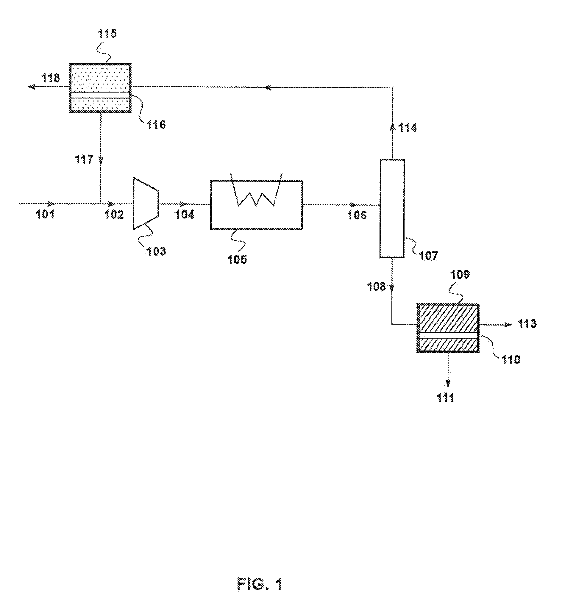
[0154]For comparison with the following examples, a calculation was performed in a process where only the uncondensed gas stream 114 from separator 107 was treated. In other words, stream 108 was withdrawn from the separator and was not further treated. The treatment included using two membrane separation steps, similar to steps 115 and 219 in FIG. 2. Likewise, the streams are labeled to correspond with the treatment process of the uncondensed gas stream represented in FIG. 2.

[0155]For the calculation, the effluent gas stream was assumed to have a flow rate of 1,139 kg / hour and contain propylene, propane, and nitrogen. It was also assumed that the molar compositions were approximately as follows:

Nitrogen: 76%

Propylene: 21%

Propane: 3%

[0156]It was further assumed that the effluent gas stream was compressed to 24 bara in compression step 103, then cooled to −20° C. in condensation step 105.

[0157]The calculation...

example 2

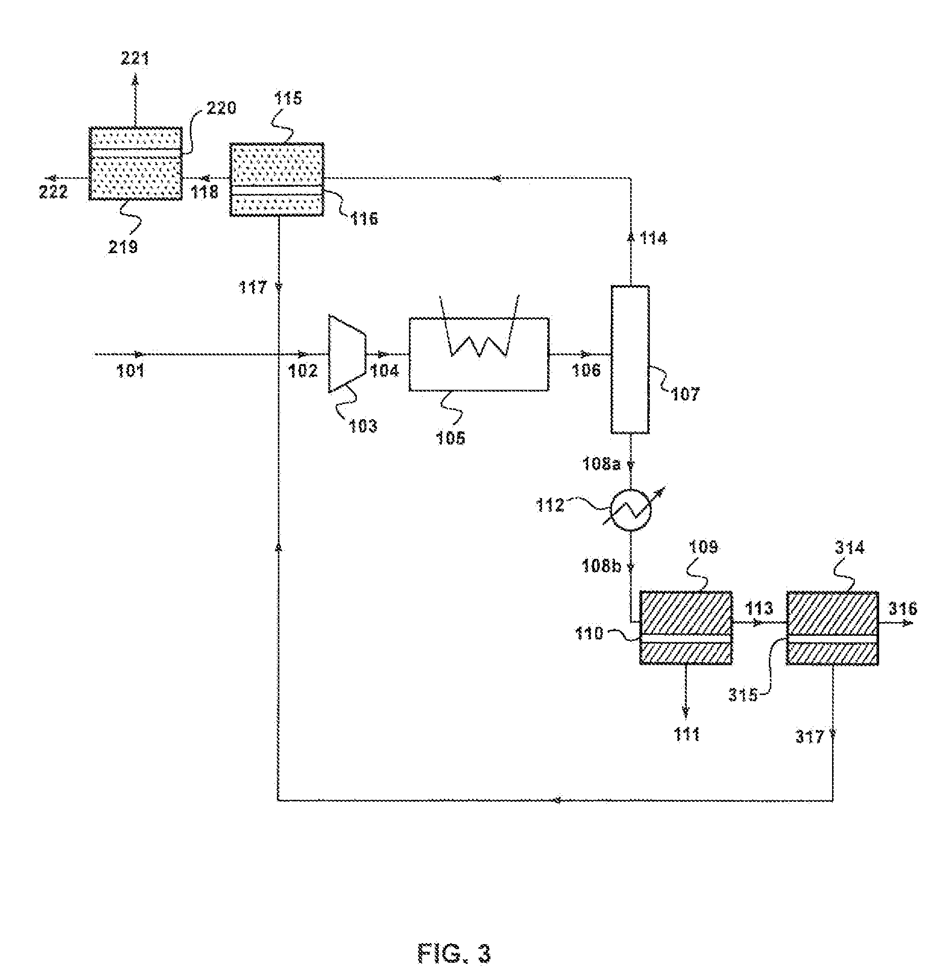
Olefin Recovery Process in Accordance with the Invention of FIG. 3

[0160]A calculation was performed to model the performance of the process of FIG. 3 in treating an effluent gas stream in a manufacturing operation. The membrane separation of the liquid condensate occurred under pervaporation conditions.

[0161]The results of the calculations are shown in Table 2.

TABLE 2Stream101108a108b111113316317114117118221222Mass1,139805805325480434372,2701,500771135636flow(kg / h)Temp70−204040403829−2028222221(° C.)Pressure1232312221123123323(bara)Component (mol %)Nitrogen75.93.83.80.56.030.03.483.261.299.097.099.5Propylene20.876.576.593.864.97.171.113.830.30.82.50.4Propane3.319.819.85.829.162.925.53.18.50.20.60.1Mass flow (kg / h)Nitrogen77020201199101,737977760129631Propylene3166186183043133310432424954Propane53167167201483111710199211

[0162]Using polymeric membranes to treat the uncondensed gas stream and inorganic membranes to treat the condensate, the process achieves 96% recovery of olefin. The ...

example 3

Olefin Recovery Process in Accordance with the Invention of FIG. 5

[0163]A calculation was performed to model the performance of the process of FIG. 5 in treating an effluent gas stream to recover olefins in a manufacturing operation. The results of the calculations are shown in Table 3.

TABLE 3Stream101108509512513114117118221222Mass flow1,139367367300682,2751,503772135637(kg / h)Temp70−20333129−2028222221(° C.)Pressure12331323123323(bara)Component (mol %)Nitrogen75.93.73.70.816.283.073.799.096.999.5Propylene20.883.183.192.941.015.023.10.82.70.4Propane3.313.213.26.242.82.13.20.10.40.1Mass flow (kg / h)Nitrogen77099281,737976761129632Propylene317307307278294704611054Propane52515120316866111

[0164]Using polymeric membranes to treat the uncondensed gas stream and an inorganic membrane to treat the condensate, the process achieves 88% recovery of olefin. The ratio of propylene to propane in purge stream 513 is reduced to less than 1:1.


PUM


Abstract

A process for treating an effluent gas stream arising from a manufacturing operation that produces an olefin or a non-polymeric olefin derivative. The process involves cooling and condensing the effluent gas stream, which comprises an olefin, a paraffin, and a third gas, to produce a liquid condensate and an uncondensed (residual) gas stream. Both streams are then passed through membrane separation steps. The membrane separation of the uncondensed gas stream results in an olefin-enriched stream and an olefin-depleted stream. The olefin-enriched stream is recirculated within the process prior to the condensation step. The membrane separation of the condensate also results in an olefin-enriched stream, which may be recycled for use within the manufacturing operation, and an olefin-depleted stream, which may be purged from the process.

Description

CROSS-REFERENCE TO RELATED APPLICATIONS[0001]This application is a continuation-in-part of U.S. application Ser. No. 14 / 486,382, filed Sep. 15, 2014, the disclosure of which is hereby incorporated herein by reference in its entirety.FIELD OF THE INVENTION[0002]The invention relates to a process for recovering olefins from a manufacturing operation. More specifically, the invention relates to treating an effluent gas stream using separation membranes for recovering olefin and separating paraffin.BACKGROUND OF THE INVENTION[0003]Olefins, such as ethylene and propylene, and their non-polymeric derivatives, such as isopropyl alcohol and cumene, account for some of the most demanded chemicals in the world. For example, the United States alone produces more than 10 billion pounds of chemicals derived from propylene annually.[0004]Olefins are commonly produced by cracking hydrocarbon feedstocks or catalytically converting oxygenate feedstocks. Traditional methods for cracking include steam...

Claims


Application Information

Patent Timeline
IPC IPC(8): C07C7/144C07C7/00C07C7/09
CPCC07C7/144C07C7/09C07C7/005B01D53/002B01D53/225B01D53/229C01B3/501B01D2256/24B01D2257/108B01D2257/702C01B2203/0405C01B2203/048Y02P20/582C07C11/04C07C11/06C07C11/08
Inventor SU, PAUL
Owner MEMBRANE TECH & RES
Why Eureka
Try Eureka